
Flat panel display device and fabrication apparatus thereof and fabrication method thereof

Active Publication Date: 2011-01-04
SAMSUNG DISPLAY CO LTD
View PDF13 Cites 8 Cited by
  • Summary
  • Abstract
  • Description
  • Claims
  • Application Information

AI Technical Summary

Benefits of technology

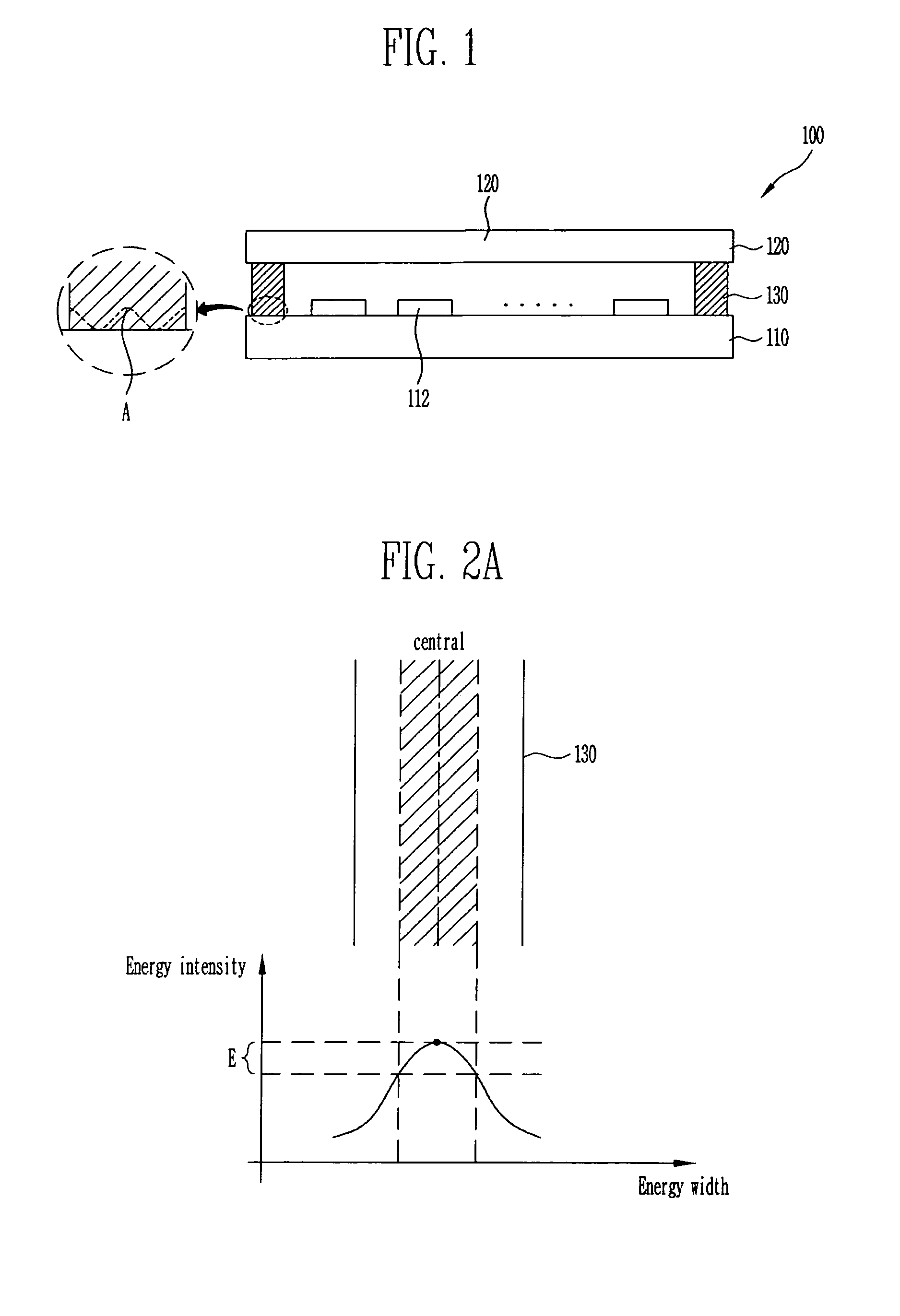
An aspect of the present invention provides a flat panel display device and fabrication method thereof for bonding a substrate on which elements are formed to a sealing member by melting the frit pattern formed on the sealing member and preventing a frit pattern from incompletely being melted by irradiating the frit pattern along at least two paths with laser when melting it.
Another aspect of the present invention provides a fabrication apparatus of a flat panel display device for preventing a frit pattern from incompletely being melted and cured by irradiating the frit pattern along at least two paths with laser when melting and bonding it.

Problems solved by technology

Applying the first laser beam may cause to melt a portion of the first elongated segment.

Method used


Image

  • Flat panel display device and fabrication apparatus thereof and fabrication method thereof
  • Flat panel display device and fabrication apparatus thereof and fabrication method thereof
  • Flat panel display device and fabrication apparatus thereof and fabrication method thereof

Examples


Embodiment Construction

Hereinafter, various embodiments of the present invention will be described with reference to the accompanying drawings.

An organic light emitting display (OLED) is a display device comprising an array of organic light emitting diodes. Organic light emitting diodes are solid state devices which include an organic material and are adapted to generate and emit light when appropriate electrical potentials are applied.

OLEDs can be generally grouped into two basic types dependent on the arrangement with which the stimulating electrical current is provided. FIG. 5A schematically illustrates an exploded view of a simplified structure of a passive matrix type OLED 1000. FIG. 5B schematically illustrates a simplified structure of an active matrix type OLED 1001. In both configurations, the OLED 1000, 1001 includes OLED pixels built over a substrate 1002, and the OLED pixels include an anode 1004, a cathode 1006 and an organic layer 1010. When an appropriate electrical current is applied to th...


PUM

PropertyMeasurementUnit
Widthaaaaaaaaaa

Abstract

Disclosed is a method of making a flat panel display device. The device has a first substrate, a second substrate opposing the first substrate and an array of pixels formed therebetween. A frit is interposed and interconnects between the first substrate and second substrate. The frit is melted by irradiating a first laser and a second laser. The first and second lasers move along the different paths.

Description

CROSS-REFERENCE TO RELATED APPLICATIONSThis application claims the benefit of Korean Patent Application Nos. 10-2006-0014325, filed Feb. 14, 2006 & 10-2006-0016427, filed Feb. 20, 2006, in the Korean Intellectual Property Office, the disclosure of which is incorporated herein by reference in their entirety.BACKGROUND1. Field of the InventionThe present invention relates to a flat panel display device, and more particularly, to encapsulating a flat panel display device.2. Discussion of Related ArtRecently, various flat panel display devices capable of reducing weight and volume, which are disadvantages of a cathode ray tube (CRT), have been developed. As the flat panel display device, there are a liquid crystal display, a field emission display, a plasma display panel and a light emitting display, etc. There have widely been studied the flat panel display devices since they can be constituted in super thin and flexible form in terms of driving characteristic. Among others, since the ...

Claims


Application Information

Patent Timeline
IPC IPC(8): H01J9/26G09F9/30H01L27/32H01L51/50H05B33/04H05B33/10
CPCB23K26/0604B23K26/0876B23K26/10H01L51/5237C03C27/06H01J9/261C03C8/24C03C2218/34H10K59/8722H10K50/8426
Inventor LEE, JONG WOO
Owner SAMSUNG DISPLAY CO LTD
Learn More