
Printing system with power saving mode

a printing system and power saving technology, applied in the field of printing systems, can solve the problems of extremely low data transfer efficiency and transmission error, and achieve the effect of avoiding the generation of time-out errors

Inactive Publication Date: 2010-12-28
FUJIFILM BUSINESS INNOVATION CORP
View PDF33 Cites 10 Cited by
  • Summary
  • Abstract
  • Description
  • Claims
  • Application Information

AI Technical Summary

Benefits of technology

[0007]The present invention has been made in view of the above subjects, and it is an object of the present invention to provide a printing system capable of avoiding the generation of the time-out error on the upper system side and also enabling the optimization of FPOT, in shifting the mode from the power-saving mode to the normal mode even when a time required for a building-up process of CPU is long.Means for Solving the Problems

Problems solved by technology

For this reason, it may be considered such a situation that, if a time required for a building-up process of CPU is long, a return time from the power-saving mode to the normal mode (normal transfer mode) exceeds a time-out time of the data transmission on the upper system side, e.g., the host computer side, to thus cause the transmission error.
At that time, since the process to transmit the data once again, to interrupt temporarily the transmission, or the like is carried out on the host computer side, there is the problem that the data transfer efficiency is extremely lowered.

Method used


Image

  • Printing system with power saving mode
  • Printing system with power saving mode
  • Printing system with power saving mode

Examples


first embodiment

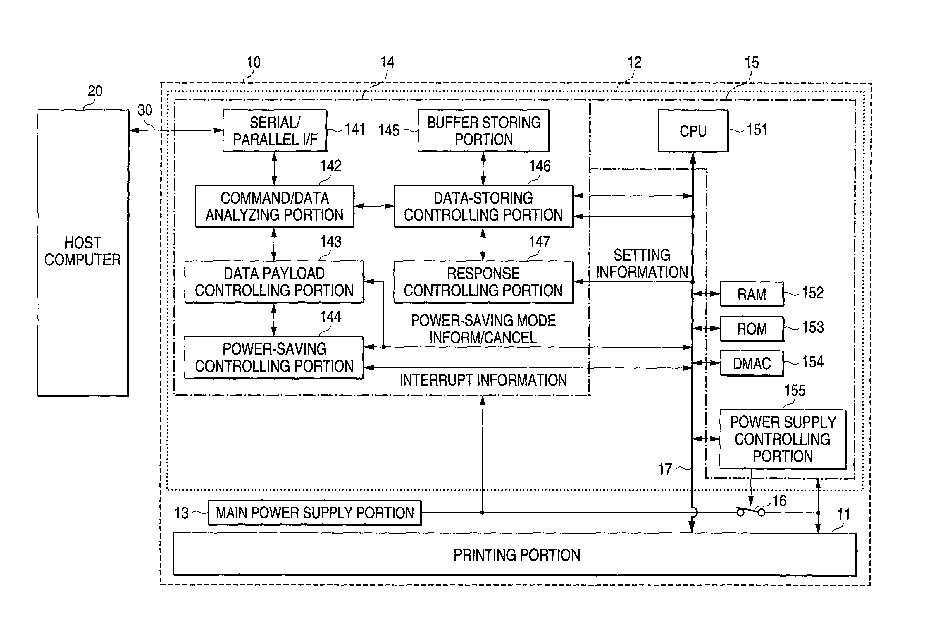
[0021]FIG.1 is a block diagram showing an outline of a configuration of a printing system according to a first embodiment of the present invention. In FIG.1, a printing system 10 of the present embodiment is constructed such that such printing system comprises a printing portion 11, a print controlling portion 12 for controlling the printing portion 11, and a main power supply portion 13, and is connected to a host computer 20 as an upper system, for example, via a serial bus 30 to transmit / receive the serial data to / from the host computer 20.

[0022]The print controlling portion 12 is constructed such that such print controlling portion has a communication I / F (interface) 14 for executing the communication with the host computer 20 via a serial bus 30, and a controlling portion 15 for controlling the overall present system, and the power source is directly supplied from the main power supply portion 13 to the communication I / F (interface) 14, and also the power source is selectively ...

second embodiment

[0052]FIG. 4 is a block diagram showing an outline of a configuration of a printing system according to a second embodiment of the present invention. In FIG. 4, a printing system 50 according to the present embodiment is constructed such that such printing system comprises a printing portion 51, a print controlling portion 52, a main power supply portion 53, and a power supply controlling portion 54, and is connected to a host computer 60 as the upper system, for example, via a parallel bus 70 to transmit / receive the parallel data to / from the host computer 60.

[0053]The print controlling portion 52 is constructed such that such print controlling portion has a communication I / F 55 for executing the communication with the host computer 60 via a parallel bus 70, and a controlling portion 56 for controlling the overall present system, and the power source is directly supplied from the main power supply portion 53 to the communication I / F 55, and also the power source is selectively suppl...


PUM


Abstract

In a printing system 10 connected to a host computer 20 as an upper system via a serial bus, communication control information used in a shift from a power saving mode to a normal transfer mode are previously in a response controlling portion 147 before a CPU 151 in a printing controlling portion 12 is shifted into the power saving mode, and then the response controlling portion 147 can receive the data based on the set communication control information without intervention of a CPU 151 in the cancel of the power saving mode.

Description

BACKGROUND OF THE INVENTION[0001]1. Technical Field[0002]The present invention relates to a printing system for receiving print data transmitted from an upper system to execute a printing process and, more particularly, a printing system having a power-saving mode that can save the power (energy) by stopping the power source and the clock supplied to a printing portion, a controlling portion, etc. in the standby state in which no printing process is executed.[0003]2. Related Art[0004]In the prior art, as the system of this type, it has been well known the system employing the system that the power supply of the system is turned ON while asserting the first output control signal (busy signal) when the receiving operation is started in the power-saving mode, and then the busy signal is negated when the initialization is completed (see Patent Application Publication (KOKAI) Hei 10-56526, for example). In other words, the receiving operation from the parallel interface is stopped once b...

Claims


Application Information

Patent Timeline
Patent Type & Authority Patents(United States)
IPC IPC(8): G06K15/00G06F3/12G06F1/00B41J29/38G06F1/32G06F13/00
CPCG06K15/00
Inventor UENO, TAKUHITOKIKUCHI, MASAHIKO
Owner FUJIFILM BUSINESS INNOVATION CORP
Learn More