
Bicycle rack for a vehicle bed

a vehicle bed and bicycle rack technology, applied in vehicle components, supplementary fittings, transportation vehicles, etc., can solve the problems of bicycle damage, bicycle damage, transportation vehicle, or both, and not necessarily sufficiently secured on the bed, so as to facilitate the use of the rack, avoid damage to the bike, and facilitate installation.

Active Publication Date: 2010-12-28
THULE SWEDEN AB +1
View PDF10 Cites 17 Cited by
  • Summary
  • Abstract
  • Description
  • Claims
  • Application Information

AI Technical Summary

Benefits of technology

[0010]Many bicyclist are also pickup truck owners who use these vehicles for transporting their bicycles. In that at least a part of the bed space is often available for such bike transporting, these consumers have established a demand for racks that can be easily installed in the bed of their trucks. These users typically have two primary desires; the first is upright stability for the bike(s) being transported and the second is avoiding permanent modification of the truck itself just to facilitate use of the rack. The first desire stems from the fact that upright transport of a bicycle resting on its tires best avoids damage to the bike when other rack contact can then be avoided. Still further, exclusive rack contact with the bike at its tires permits the tires to act as buffers against the rack. Still further, the resilient nature of inflated tires permits their acting as take-up devices that eliminate play between the bike and a carrying rack that has slightly relaxed its grip upon the bike tire during transport.
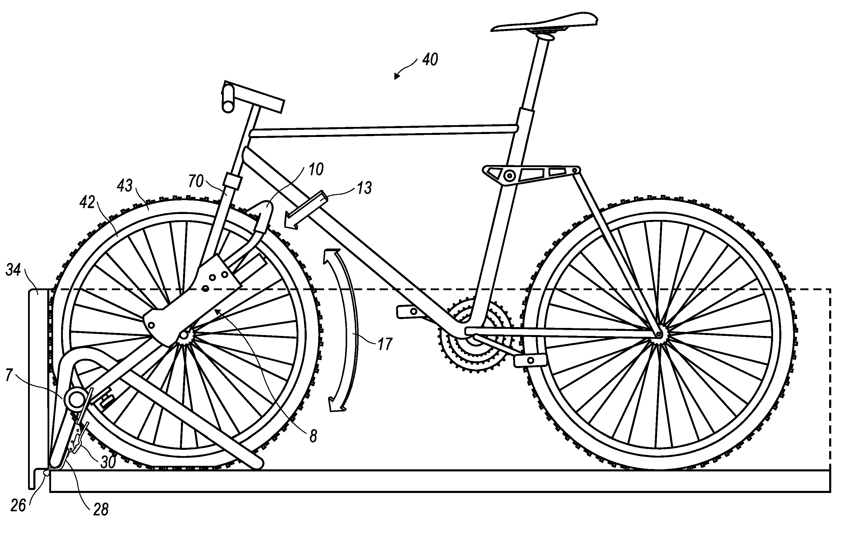
[0011]It has also been recognized as a benefit to have such tire-constrained bicycles stabilized with respect to the carrying truck bed. Advantageously, the present invention provides such stability by compressing the tire into pressing engagement with the truck bed at one or more locations. It has been found particularly advantageous to locate the bike rack in the truck bed so that when a bike tire is properly installed and secured, the tire is press-engaged with a vertical surface such as the interior surface of the tailgate or sidewall of the bed. Alternatively, or in addition to the vertical surface contact, the tire can also be advantageously press-engaged with a horizontal surface of the truck bed such as the bed floor, or the rack itself.

Problems solved by technology

While such techniques are relatively simple, the loaded equipment is not necessarily sufficiently secured upon the bed.
Indeed, when transporting a bicycle in this manner it is not uncommon for the bicycle to shift, which can damage the bicycle, the transporting vehicle, or both.
Additionally, in some instances, bicycles loaded in this manner can fall out during transport and cause severe damage or injury.
While assemblies have been developed for loading and securing bicycles, and like wheeled vehicles, into vehicle beds, such assemblies have generally proved insufficient for conveniently transporting or preventing damage to the bicycle or transporting vehicle.
A problem with this known assembly is that holes must be drilled into the bed of the vehicle.
The removal of the front wheel is not only an inconvenience to a user, but more importantly, a bicycle rack that attaches the bicycle via the forks may not be capable of accommodating a variety of bicycle fork types, e.g., racing, touring, mountain, BMX, etc., bicycle forks.
A problem with this type of assembly is that these assemblies are usually only secured against the sidewalls of a vehicle bed and have a tendency to shift or work themselves loose during transport.
This allows the assembly to become unsecured and possibly cause damage or injury.
Also, because the tension provided by the crossbar or strap is the primary means for securing the assembly between the sidewalls of the vehicle, if the tension in the crossbar or straps is reduced, as may occur through loosening or failure, the bicycle may also become loose or free and possibly cause damage or injury.
Also, while some known assemblies are capable of accommodating bicycles with their front wheels installed, such assemblies typically do not provide sufficient securement to the bed of a vehicle, do not sufficiently secure a bicycle within the assembly, or require the removal of a wheel of the bicycle.
A problem with this known assembly, however, is that a wheel of a bicycle must be removed and secured via the forks of the bicycle.
As previously noted, these types of assemblies are undesirable because they lack the ability to secure a variety of bicycles having different fork structures and the wheels must be removed and separately stowed, and too often, the user simply rests the separated wheel in the bed of the vehicle where it can shift about and cause damage.
U.S. Pat. Nos. 5,092,504 and 6,367,673 disclose bicycle racks for use in truck beds, but each disclosed arrangement detrimentally requires that the front wheel of the bicycle be removed in order to use the rack.
U.S. Pat. No. 4,852,779 discloses a truck bed rack for a motorcycle in which the front wheel remains installed on the bike when being transported, but modification of the truck is undesirably required (Column 3, lines 15-20) in that U-bolts are used to rigidly secure an anchor sleeve to the bed of the automotive vehicle.
Still further, the use of hooked elastic bands connect directly to the bike frame and not the bike's front tire which lends less stability to the system than direct connection to the front tire of the bike which results in fixed location of that tire during transport.
In addition to not being mountable in a truck bed, this rack's specialized configuration enabling such hitch mounting teaches away from any type of adaptation to that rack which would permit its mounting at any other location on a carrying vehicle, and especially not with the carried bicycle(s) being located at a fixed position above the bed of a truck during transport.

Method used


Image

  • Bicycle rack for a vehicle bed
  • Bicycle rack for a vehicle bed
  • Bicycle rack for a vehicle bed

Examples


Embodiment Construction

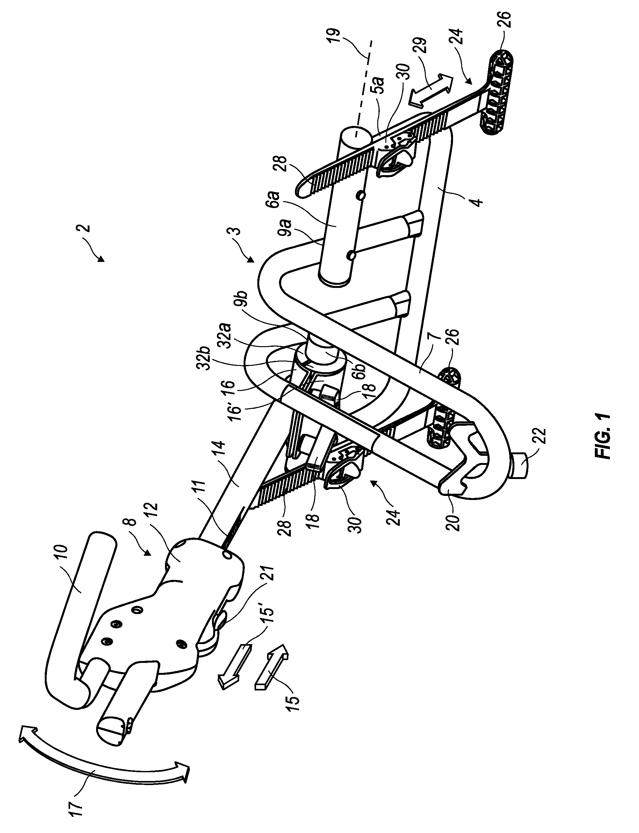
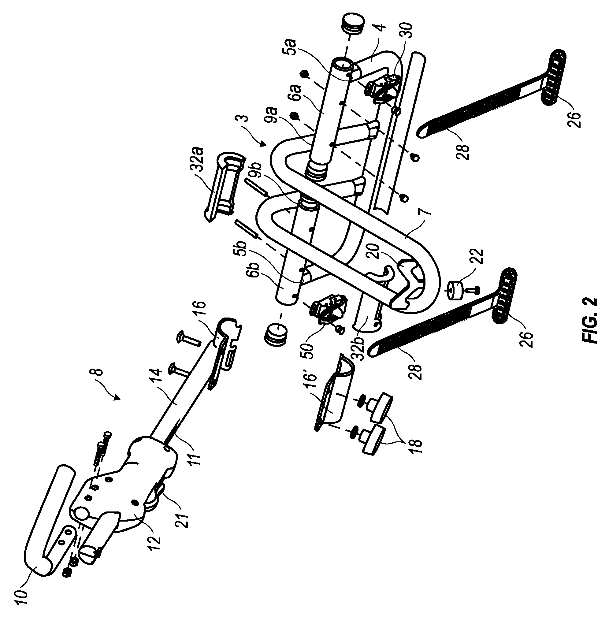
[0041]The present invention will now be more described and disclosed in greater detail. It is to be understood, however, that the disclosed embodiments are merely exemplary of the invention and that the invention may be embodied in various and alternative forms. It should also be understood that the accompanying figures are not necessarily to scale and some features may be exaggerated, or minimized, to show details of particular components. Therefore, specific structural and functional details disclosed herein are not to be interpreted as limiting the scope of the claims, but are merely provided as an example to teach one having ordinary skill in the art to make and use the invention. It should also be appreciated that in the detailed description that follows, like reference numerals on different drawing views are intended to identify like structural elements. It should also be appreciated that while the present invention is primarily described as a rack assembly primarily configure...


PUM


Abstract

Method and arrangement for providing a bicycle transport system that includes a rack assembly securing a bicycle, with both wheels still attached, in the bed of a pickup truck without requiring physical modification of the pickup truck bed. The transport system includes a rack frame having a securing assembly releasably securing the rack frame in the bed of a transporting pickup truck. The system also includes a bicycle restraining portion that is maintained in abutting engagement with a front tire of a bicycle being transported in the pickup truck bed. The securing assembly has an anchor member that in a secured configuration maintains the rack frame in abutment with the pickup truck bed so that the rack frame is substantially fixing relative to the truck bed. The bicycle restraining portion has a constrictable arm that presses upon the front tire of the bicycle in a transporting configuration. The arm exerts a compression force, obliquely directed with respect to both horizontal and vertical, upon the bicycle front tire in such a manner that the tire is compressed into a substantially fixed position above the truck bed when in the bicycle transporting configuration.

Description

CROSS REFERENCE TO RELATED APPLICATIONS[0001]This application claims the benefit of U.S. Provisional Patent Application No. 60 / 592,419, filed Jul. 30, 2004, the same being expressly incorporated herein by reference.TECHNICAL FIELD OF THE INVENTION[0002]The present invention relates to load carriers for vehicles, and more particularly to a rack assembly for securing wheeled vehicles, such as bicycles, tricycles, mopeds, motorcycles and the like, over the bed structure of a vehicle, such as that of a pickup truck.BACKGROUND OF THE INVENTION[0003]The transportation of wheeled vehicles, such as bicycles, tricycles, mopeds, motorcycles and the like using vehicle load carriers is known and vehicle load carriers for transporting wheeled vehicles, such as bicycles, typically includes the use of roof mounted type load carriers, also known as roof racks, or rear mounted type load carriers, which are often fastened to the rearward side of a vehicle or upon the hitch of a vehicle.[0004]When tra...

Claims


Application Information

Patent Timeline
Patent Type & Authority Patents(United States)
IPC IPC(8): B60R9/10
CPCB60P3/077B60R9/10
Inventor REEVES, MIKESTARR, ROBERT A.RAYL, ERIC
Owner THULE SWEDEN AB
Learn More