Wheel for vehicles

a technology for vehicles and wheels, applied in the field of wheels for vehicles, can solve the problems of powering units, inability to fully exploit the kinetic energy generated by rolling of tyres, and complex installation of the same,

Inactive Publication Date: 2010-12-28
PIRELLI TYRE SPA
View PDF20 Cites 29 Cited by
  • Summary
  • Abstract
  • Description
  • Claims
  • Application Information

AI Technical Summary

Benefits of technology

[0023]The Applicant has finally found that use of an electric generator comprising a stator, mounted on a first element adapted to be linked to the rim or the tyre, and a rotor installed on a second element free to rotate relative to the first one around a predetermined rotation axis and provided with a mass centre eccentric to said predetermined rotation axis, enables the previously depicted problems to be solved.
[0063]In this way all the detecting system is disposed at the inside of the tyre, the empty space within the tyre is utilised and this system can be easily replaced during replacement of the tyre itself.

Problems solved by technology

The Applicant has noticed that, since as regards the antenna and the device for generating the magnetic field described in document WO 2006 / 048899 mounting of elements on the vehicle is required, installation of same needs modification of the vehicle itself and is therefore complicated.
The Applicant has further found that the powering unit of document WO 2005 / 067073 is not able to fully exploit the kinetic energy generated by rolling of the tyre.
In fact, deformation of the piezoelectric element, due to the forces acting on the mass, is necessarily limited by the presence of the container's inner wall performing the function of stop limit, under pain of breakage of the piezoelectric element itself.
Therefore, forces of inertia that, in the absence of said stop limit, would cause a greater deformation of the piezoelectric element cannot be fully converted into electric energy.
The Applicant has also observed that the resonant oscillating mass described in document U.S. Pat. No. 5,941,692 must necessarily be installed on one side of the wheel with the oscillation axis parallel to the rotation axis of the wheel itself, so that the centripetal force and the force of gravity may cause oscillation of same, and this constraint is a limitation in terms of flexibility of use.

Method used


Image

  • Wheel for vehicles
  • Wheel for vehicles
  • Wheel for vehicles

Examples


Embodiment Construction

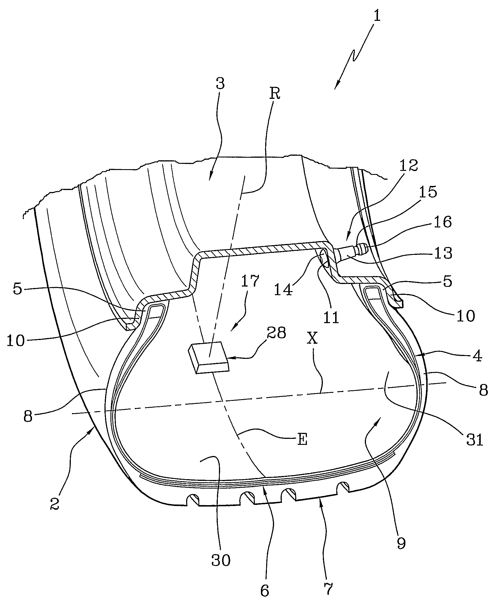
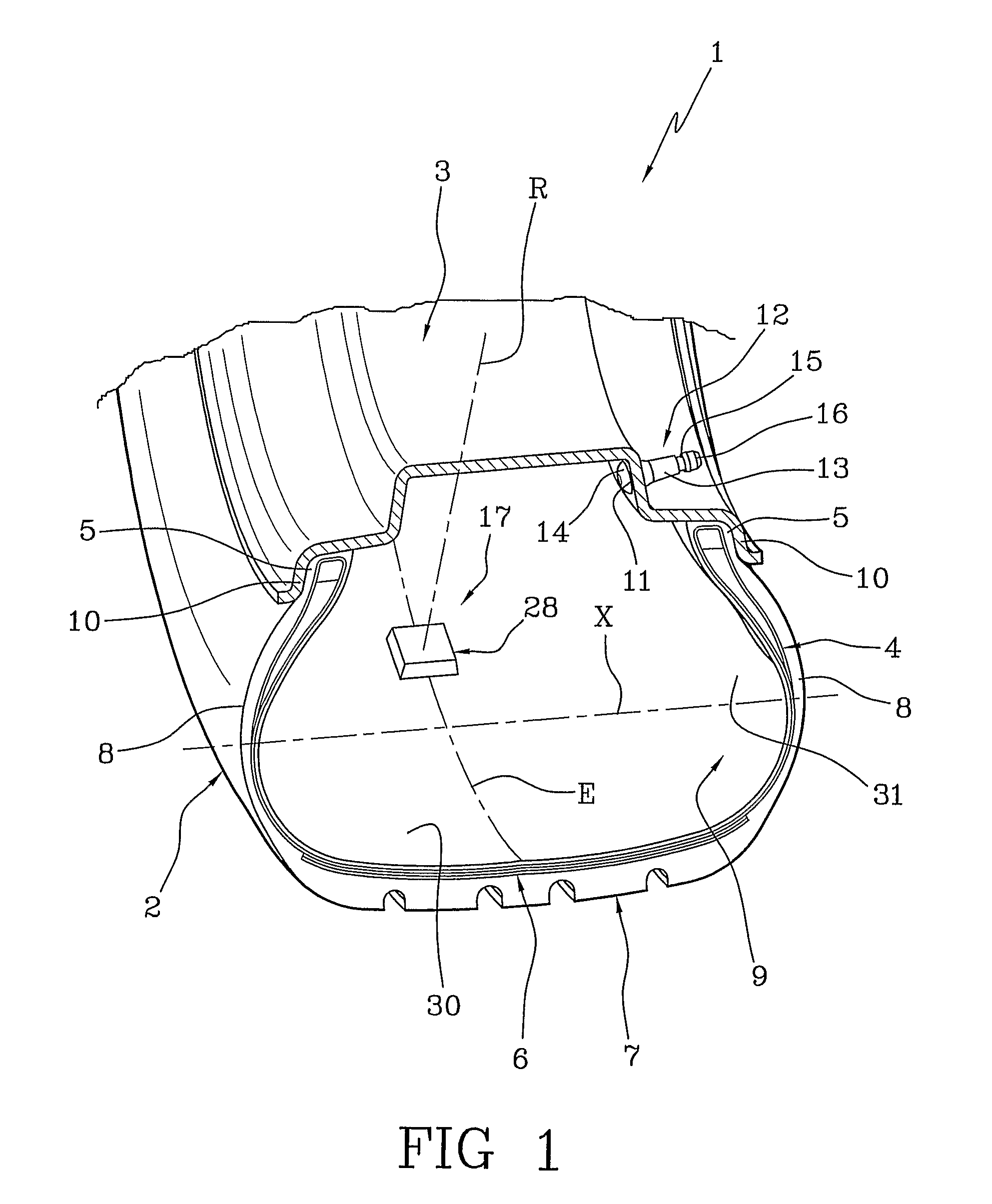
[0072]FIG. 1 shows a first preferred embodiment of the wheel 1 in accordance with the invention, which comprises a tyre 2 mounted on a rim 3.

[0073]The wheel 1 can be mounted on any type of vehicle, i.e. for example cars, vehicles for goods transportation, such as trucks and full trailers or lorries, motor-vehicles, etc.

[0074]More particularly, tyre 2 is preferably designed to be used on vehicles provided with electronic devices installed on board and suitable for co-operating and interacting with further devices that are housed on or in the wheel 1 and will be described below.

[0075]Tyre 2 comprises a carcass structure 4, the same carcass structure 4 having at least one carcass ply, not shown in detail, shaped into a substantially toroidal conformation and in engagement, by its opposite circumferential edges, with a pair of annular anchoring structures, each of which is placed in a region 5 usually identified as “bead”.

[0076]In particular, two annular anchoring structures are mutuall...


PUM


Abstract

A wheel for vehicles includes a rim, a tyre mounted on the rim, and at least one device for energy generation operatively associated with the tyre. The device for energy generation includes a first element that is fixed relative to the rim or to the tyre, and a second element mounted on the first element and free to rotate relative to the first element around a predetermined rotation axis. The second element has a mass centre eccentric to the predetermined rotation axis. The device for energy generation further includes an electric generator having a stator mounted on the first element and a rotor mounted on the second element.

Description

CROSS REFERENCE TO RELATED APPLICATION[0001]This application is a national phase application based on PCT / IT2006 / 000591, filed Jul. 28, 2006, the content of which is incorporated herein by reference.BACKGROUND OF THE INVENTION[0002]1. Field of the Invention[0003]The present invention relates to a wheel for vehicles. In particular, the present invention relates to wheels provided with devices for generating electric energy needed for powering devices installed in the tyre or on the rim of said wheel.[0004]2. Description Of Related Art[0005]These devices are, for instance, defined by detecting units capable of monitoring the operating conditions (pressure and temperature, for example) of the tyres and possibly adapted to keep a trace of the evolution in time of parameters representative of this operation, or they can be embodied by actuators such as pumps adapted to keep pressure within the tyre substantially constant.[0006]The parameters that are generally considered may be identific...

Claims


Application Information

Patent Timeline
Patent Type & Authority Patents(United States)
IPC IPC(8): B60C23/02
CPCB60C23/041H02K7/1846H02K7/1853
Inventor MANCOSU, FEDERICOBRUSAROSCO, MASSIMO
Owner PIRELLI TYRE SPA
Why Eureka
Try Eureka