
Shower drainage outlet in aircraft

a technology for aircraft and showers, applied in water installations, baths, constructions, etc., can solve problems such as mechanical destruction or increased leakage, and achieve the effect of increasing mechanical flexibility

Inactive Publication Date: 2010-12-28
AIRBUS OPERATIONS GMBH
View PDF19 Cites 3 Cited by
  • Summary
  • Abstract
  • Description
  • Claims
  • Application Information

AI Technical Summary

Benefits of technology

[0009]In this way, during installation of the shower drainage outlet, the first part may be inserted from above into the opening of the shower tub until the bearing region rests against the top of the shower tub. In this way an area-shaped tight connection between the bearing region of the first part of the shower drainage outlet and the shower tub may be provided. In this arrangement the first part may be displaced relative to the shower tub without this reducing the sealing integrity.
[0014]According to a further exemplary embodiment of the present invention, an overlap between the bearing region and the top of the shower tub is provided so that displacement between the bearing region and the top of the shower tub may not result in a reduction in the sealing integrity between these two elements, wherein as a result of this overlap horizontal tolerances between the shower tub and the waste water pipe may be compensated for.
[0025]According to a further exemplary embodiment of the present invention, the shower drainage outlet is designed such that a single or double or treble floor structure can be used. In this arrangement the thickness of the floor structure is immaterial because the first part can be slid into the second part from above, and the slide-in length can be varied accordingly. In this way vertical tolerances are compensated for, and floors of different thickness can be used.
[0027]In this way a complete waste water system for an aircraft may be provided, which may be connected to any type of shower tub through multi-layer or single-layer floor structures of any thickness. Furthermore, the waste water system according to the invention may be characterised by increased mechanical flexibility, which may make it possible for said waste water system to compensate for both vertical and horizontal tolerances. These tolerances can, for example, occur during flight, since in this phase enormous differences in pressure or temperature may occur, as a result of which differences the geometry of the fuselage changes.

Problems solved by technology

If the discharge container (wash basin or shower tub) is connected to the pipe work (waste water system) by way of a shower drainage outflow, horizontal, vertical and angular tolerances between the components to be connected may result in stress in the connection elements, which stress may result in mechanical destruction or increased leakage.

Method used


Image

  • Shower drainage outlet in aircraft
  • Shower drainage outlet in aircraft

Examples


Embodiment Construction

[0031]In the following description of the FIGURE the same reference characters are used for identical or similar elements.

[0032]The drawings are diagrammatic. They are not suitable for showing dimensions or proportions.

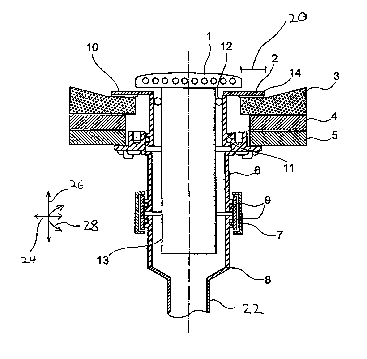
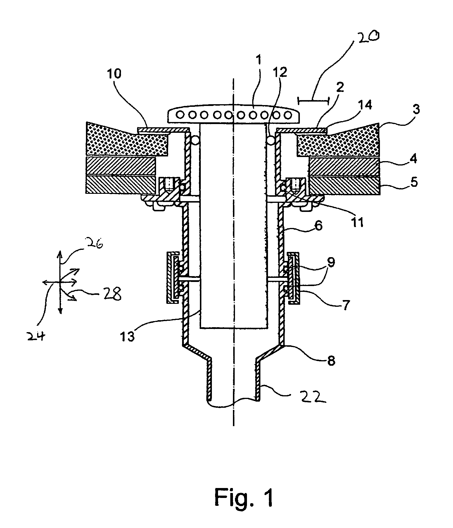
[0033]As shown in FIG. 1, the shower drainage outlet comprises a first part 2, a second part 6 and a third part 8. In this arrangement the first part 2 (shower tub outflow) can be slid from above into an opening in the shower tub 3. In this arrangement the bearing region (surface) 10 of the first part 2 comes to rest against the top of the shower tub 3. As a result of an overlap 20 between the bearing region 10 and the top of the shower tub 3, horizontal tolerances may be compensated for, without this leading to a loss of the sealing integrity in the region of the bearing region 10.

[0034]In order to enhance the sealing integrity, a sealing element 14 may be provided, which is, for example, designed in the form of a coating, film, sealing mat, o-ring or the like.

[0035]...


PUM


Abstract

A shower drainage outlet for a shower tub in an aircraft is stated, which shower drainage outlet comprises three parts that can be displaced, angled or rotated in relation to one another. In this way horizontal, vertical and angular tolerances can be compensated for. Furthermore, the shower drainage outlet is designed to be inserted through an opening in the floor region of the aircraft.

Description

CROSS-REFERENCE TO RELATED APPLICATIONS[0001]This application claims the benefit of the filing date of German Patent Application No. 10 2006 004 225.5 filed Jan. 30, 2006 and of U.S. Provisional Patent Application No. 60 / 763,441 filed Jan. 30, 2006, the disclosures of which are hereby incorporated herein by reference.FIELD OF THE INVENTION[0002]The present invention relates to shower drainage outlets for aircraft. In particular, the present invention relates to a shower drainage outlet for a shower tub in an aircraft, to a waste water system for an aircraft, as well as to the use of a corresponding shower drainage outlet in an aircraft.TECHNOLOGICAL BACKGROUND OF THE INVENTION[0003]In aircraft, waste water systems are used to collect or discharge to the outside the waste water from wash basins or sinks, as well as the water from galleys. Up to now the wash basins, the drainage outlets from galleys, as well as the air humidifiers of the air conditioning system have been connected to ...

Claims


Application Information

Patent Timeline
Patent Type & Authority Patents(United States)
IPC IPC(8): A47K3/022E03C1/26
CPCB64D11/02E03C1/20E03C1/264
Inventor SCHEEL, MARCGUTTAU, SIMONEHEUER, GUNNAR
Owner AIRBUS OPERATIONS GMBH
Learn More