
Packet transfer method and apparatus

a packet transfer and packet technology, applied in the field of packet transfer methods and apparatuses, can solve the problems of reducing communication efficiency, unable to recognize the guaranteed bandwidth (guaranteed rate) of the line in real time, and unable to maximize the effective use of the line servi

Inactive Publication Date: 2010-12-21
FUJITSU LTD
View PDF10 Cites 2 Cited by
  • Summary
  • Abstract
  • Description
  • Claims
  • Application Information

AI Technical Summary

Benefits of technology

The present invention provides a method and apparatus for transferring packets by a partial rate guaranteed service, which reduces the amount of packets discarded within a network. The method involves setting a partial rate guaranteed service on an available line with an opposed device, establishing a TCP tunnel with the opposed device, and encapsulating a packet to be passed through the TCP tunnel when the destination of the packet indicates the opposed device. The priority of the packet can be determined based on its importance or bandwidth requirements, and the packet can be registered separately in either a buffer for the TCP tunnel or another buffer. The use of a partial rate guaranteed service and a TCP tunnel ensures high-quality communication for important data and avoids slowdowns due to data discard between end users.

Problems solved by technology

When such a partial rate guaranteed service is applied to the relay line between routers, the routers can not recognize the guaranteed bandwidth (guaranteed rate) of the line in real time.
Otherwise, effective use of the line service can not be maximized if the transmission at the maximum rate is not performed although it is actually enabled.
As a result, there is a problem that retransmission packets are increased within the network and the slow start control of the communication between the end users due to the packet discard results in the reduction of the communication efficiency.

Method used


Image

  • Packet transfer method and apparatus
  • Packet transfer method and apparatus
  • Packet transfer method and apparatus

Examples


Embodiment Construction

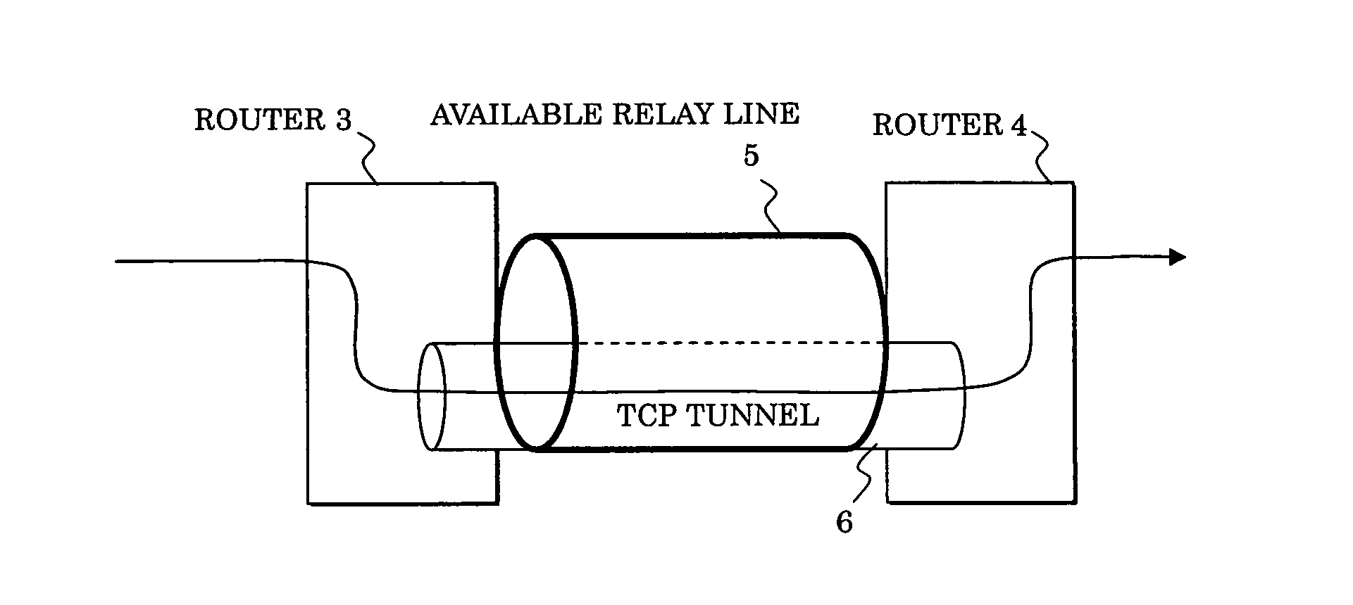
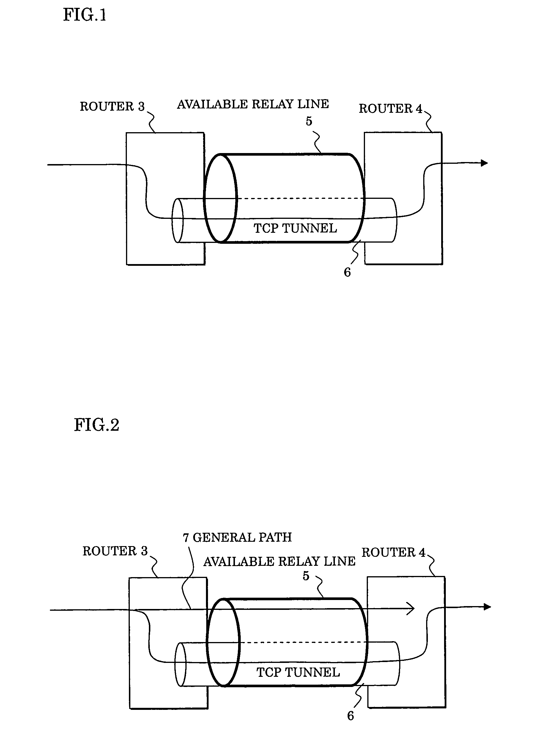
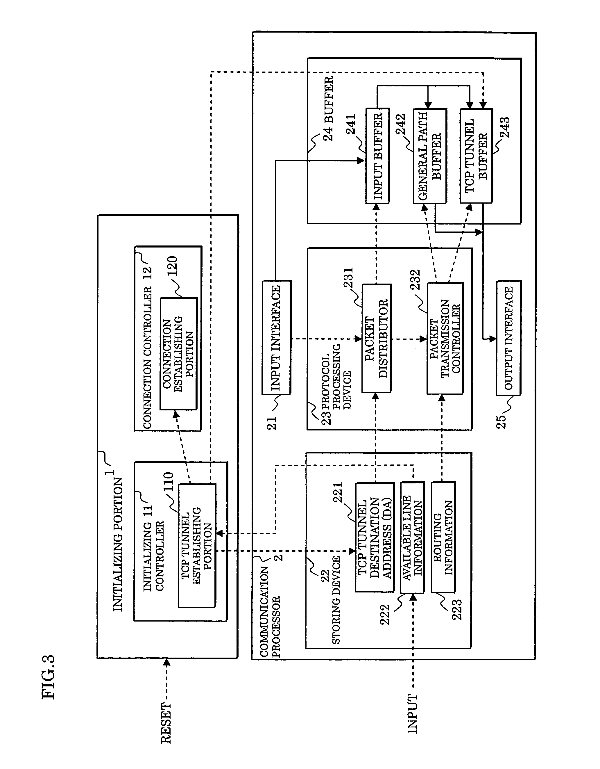
[0047]FIG. 3 shows a packet transfer apparatus realizing a packet transfer method according to the present invention. This packet transfer apparatus is provided in the router 3 on the transmission side shown in FIGS. 1 and 2, and is composed of an initializing (initial setting) portion 1 and a communication processor 2.

[0048]The initializing portion 1 includes an initializing controller 11 and a connection controller 12. The initializing controller 11 includes a TCP tunnel establishing portion 110, and the connection controller 12 includes a connection establishing portion 120.

[0049]Also, the communication processor 2 is composed of an input interface 21, a storing device 22, a protocol processing device 23, a buffer 24, and an output interface 25.

[0050]The storing device 22 among them includes a TCP tunnel destination address (DA) 221, available line information 222, and routing information 223.

[0051]Also, the protocol processing device 23 includes a packet distributor 231 and a pa...


PUM


Abstract

When a partial rate guaranteed service is applied to a communication line connecting predetermined routers, a TCP tunnel (TCP connection) is established between the routers, a packet whose destination is a router connected to the communication line is passed through the TCP tunnel, and other packets of an application using a UDP of a VoIP or the like are forwarded by a normal routing control without being passed through the TCP tunnel.

Description

CROSS-REFERENCE TO RELATED APPLICATION[0001]This application is a continuation of International Application PCT / JP03 / 09196 filed on Jul. 18, 2003, the contents of which are herein wholly incorporated by reference.BACKGROUND OF THE INVENTION[0002]1. Field of the Invention[0003]The present invention relates to a packet transfer method and apparatus, and in particular to a packet transfer method and apparatus in a relay line between routers.[0004]2. Description of the Related Art[0005]Services of a network carrier using an ATM (Asynchronous Transfer Mode) technology include the following two services:[0006](1) CBR (Constant Bit Rate) type: Rate guaranteed service guaranteeing a fixed bandwidth;[0007](2) GFR (Guaranteed Frame Rate) type: Partial rate guaranteed service (or rate semi-guaranteed service) having both of a best-effort part and a guaranteed part (guaranteed rate part).[0008]In the above-mentioned rate guaranteed service (1), a fixed rate is constantly guaranteed. Namely, the...

Claims


Application Information

Patent Timeline
Patent Type & Authority Patents(United States)
IPC IPC(8): H04L12/28H04L12/66H04L12/46H04L47/6275
CPCH04L12/4633H04L12/5695H04L12/66H04L47/15H04L47/193H04L47/2408H04L47/2416H04L47/805H04L47/825H04L69/16H04L69/161H04L69/163H04L69/164H04L2012/5651H04L47/70
Inventor HASEGAWA, TOHRUSHIRAI, NOBUO
Owner FUJITSU LTD
Learn More