Fuel cell stack, installation structure of fuel cell stack, method of transporting fuel cell stack, and method of mounting fuel cell stack on vehicle

a technology of fuel cell stack and installation structure, which is applied in the direction of cell components, cell component details, electrochemical generators, etc., can solve the problems of increased cost, increased strength, and difficulty in transporting fuel cell stacks

Active Publication Date: 2010-12-14
TOYOTA JIDOSHA KK
View PDF21 Cites 5 Cited by
  • Summary
  • Abstract
  • Description
  • Claims
  • Application Information

AI Technical Summary

Benefits of technology

[0005]Here, it can be conceived that suspension hangers can be attached to the fuel cell case to facilitate the suspension of the fuel cell case. However, in this case, as the fuel cell stack is heavy, it is necessary for the suspension hangers to have the strength sufficient to bear the suspension of the fuel cell case while being transported. Also, a problem is that when the case strength is increased, merely for transportation, the strength exceeds that required in use, and costs are increased.
[0006]The present invention is provided while taking the above described situation into account, and one objective of the invention is to provide a fuel cell stack that can be easily transported without increasing costs, an installation structure for the fuel cell stack, a transportation method for the fuel cell stack, and a method for mounting the fuel cell stack in a vehicle.
[0011]Since the fastening members are used to fasten the pile of fuel cells and are constituted so that they have a predetermined strength, and the rigidity is higher than that of the other stack structural members. Therefore, according to the present invention, suspension hangers are attached to rigid fastening members, and easy transportation of the fuel cell stack is directly enabled by using the suspension hangers. After the transportation of the fuel cell stack has ended, the suspension hangers may either be removed from the fastening members or be retained as fixed.
[0017]According to the present invention, conduction outside the fuel cell stack through the suspension hangers is prevented.

Problems solved by technology

However, in a case wherein the fuel cell case is formed of steel plate, aluminum or the like, transportation of the fuel cell stack is difficult.
However, in this case, as the fuel cell stack is heavy, it is necessary for the suspension hangers to have the strength sufficient to bear the suspension of the fuel cell case while being transported.
Also, a problem is that when the case strength is increased, merely for transportation, the strength exceeds that required in use, and costs are increased.

Method used


Image

  • Fuel cell stack, installation structure of fuel cell stack, method of transporting fuel cell stack, and method of mounting fuel cell stack on vehicle
  • Fuel cell stack, installation structure of fuel cell stack, method of transporting fuel cell stack, and method of mounting fuel cell stack on vehicle
  • Fuel cell stack, installation structure of fuel cell stack, method of transporting fuel cell stack, and method of mounting fuel cell stack on vehicle

Examples


Embodiment Construction

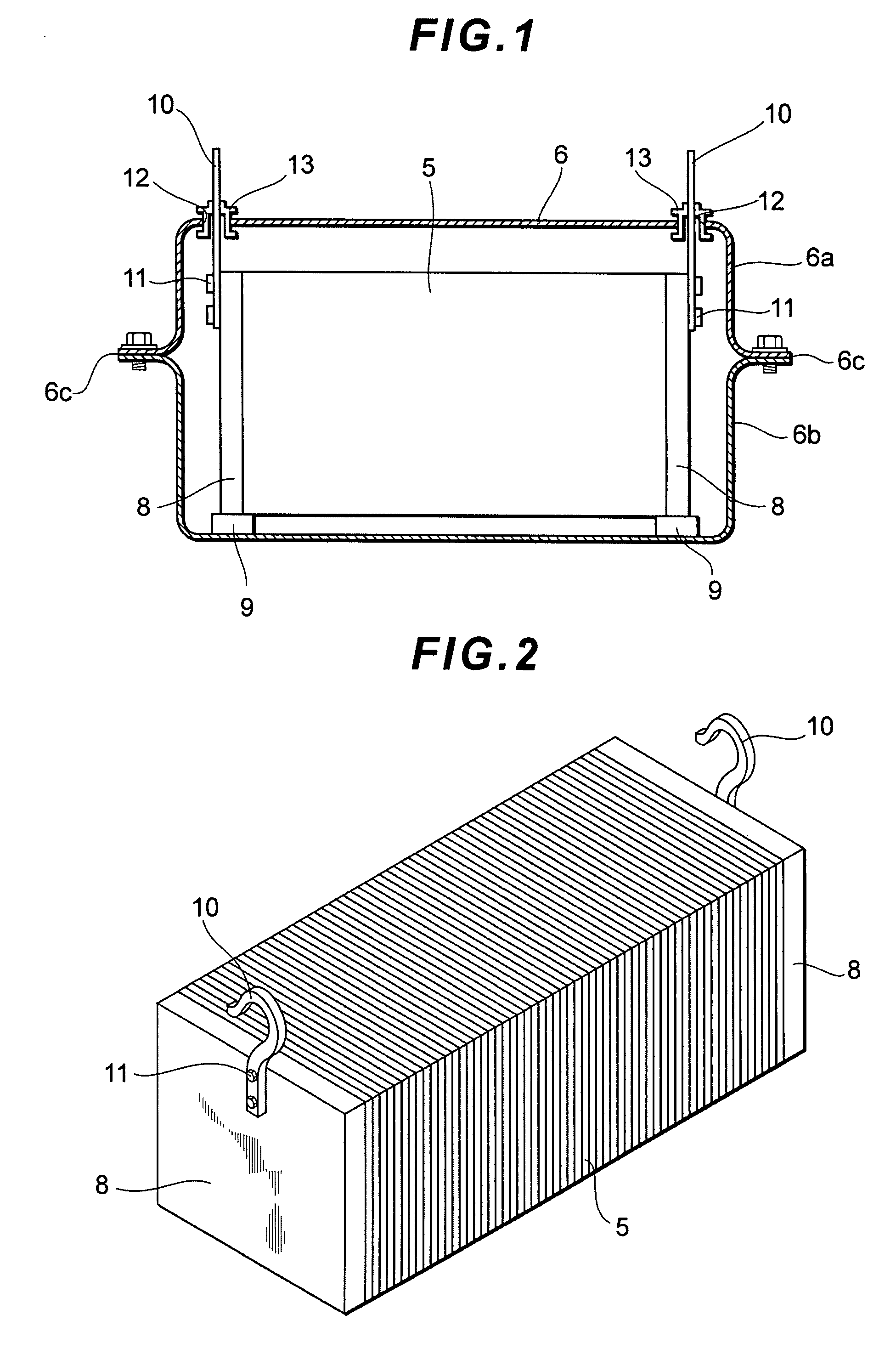
[0043]One mode of the present invention will now be described while referring to drawings. FIG. 1 is a side cross-sectional view of a fuel cell stack, and FIG. 2 is a perspective view of the fuel cell stack, not shown is a case that will be described later. Further, FIG. 3 is a side cross-sectional view of the general structure of the fuel cell stack.

[0044]First, referring to FIG. 3, an explanation will be given for the general structure of the fuel cell stack that is also applied for the fuel cell stack of this mode. A fuel cell stack of a solid polymer electrolyte type used for a vehicle is employed for the following explanation, but the fuel cell stack is not limited to this example.

[0045]A stack body 5 shown in FIG. 3 is constituted so that it includes a pile of fuel cells, which is formed by laminating a plurality of cells 19 each including a membrane-electrode assembly (MEA) and a separator.

[0046]The stack body 5 is constituted such that terminals (electrode plates) 20, insula...


PUM

PropertyMeasurementUnit
voltageaaaaaaaaaa
voltageaaaaaaaaaa
lengthaaaaaaaaaa

Abstract

In order to easily transport a fuel cell stack, without increasing costs, the fuel cell stack according to the present invention includes a stack body 5 in which end plates 8, 8 are arranged at both ends in a cell lamination direction, and suspension hangers 10 provided on the end plates 8, 8. The suspension hangers 10 project outward from a case 6 in which the stack body 5 is stored. With this arrangement, the fuel cell stack can be suspended from outside the case 6, and transported. Also using the suspension hangers 10, this fuel cell stack can be secured in a predetermined installation location.

Description

[0001]This is a 371 national phase application of PCT / JP2006 / 302218 filed 02 Feb. 2006, claiming priority to Japanese Patent Application No. 2005-026930 filed 02 Feb. 2005, the contents of which are incorporated herein by reference.TECHNICAL FIELD[0002]The present invention relates to a fuel cell stack, an installation structure of a fuel cell stack, a method for transporting a fuel cell stack and a method for mounting a fuel cell stack in a vehicle, and relates particularly to a technique for simplifying the transportation of the fuel cell stack without increasing costs.BACKGROUND ART[0003]A fuel cell stack of a solid polymer electrolyte type, for example, is provided by laminating modules, each of which is obtained by one or more cells superposed one on another, with each cell including a membrane-electrode assembly (MEA) and a separator. The MEA includes an electrolytic membrane that is provided by an ion exchange membrane, an electrode (an anode) formed of a catalytic layer and ...

Claims


Application Information

Patent Timeline
Patent Type & Authority Patents(United States)
IPC IPC(8): H01M2/20
CPCH01M8/247H01M8/0247H01M8/2465H01M2250/20Y02E60/50Y02T90/32Y02T90/40
Inventor TANAKA, HIDEYUKI
Owner TOYOTA JIDOSHA KK
Why Eureka
Try Eureka