Eureka AIR delivers breakthrough ideas for toughest innovation challenges, trusted by R&D personnel around the world.

Hand-held power tool with a holding device

a technology locking devices, which is applied in the direction manufacturing tools, and portable power tools. it can solve the problems of negative repercussions on the handling of hand-held power tools, no defined position of tools, and user's only difficulty in holding tools, etc., and achieves economic manufacturing, simple handling, and economic manufacturing of locking devices.

Inactive Publication Date: 2005-01-27
HILTI AG
View PDF8 Cites 34 Cited by
  • Summary
  • Abstract
  • Description
  • Claims
  • Application Information

AI Technical Summary

Benefits of technology

[0012] Advantageously, the catch element pivots relative to the housing about a pivot axis into an operational position to position the catch element outside of the grasp region, insuring a problem-free grasping of the handle by the user for guiding the power tool.
[0016] Advantageously, the locking device cooperates with both the housing and the catch element with one of the housing and the catch element having at least one recess and another of the housing and the catch element having at least one locking element engaging in the recess in the holding position of the locking device. Such a locking device insures its economical manufacturing, on one hand, and, on the other hand, its simple handling.
[0017] Advantageously, the locking element (elements) is (are) retained in the respective recess(es) with a preload. This likewise insures an economical manufacturing of the locking device.
[0018] In order to insure a favorable suspension of the power tool on an object, e.g., on a belt, the free end of the catch element extends parallel to the tool plane. Thus, the free end of the catch element can be hooked on the belt of a user, securing the power tool on the user or an object with a possibility of an easy removal of the power tool.

Problems solved by technology

A drawback of the known power tool consists in that the suspended tool has no defined position and can pivot into a position in which a user can take hold of the tool only with much difficulty.
In particular in applications in which the user needs one hand for holding an object, this circumstance, i.e., the absence of a definite position of the tool in its suspended position, have very negative repercussions on the handling of the hand-held power tool.

Method used


Image

  • Hand-held power tool with a holding device
  • Hand-held power tool with a holding device
  • Hand-held power tool with a holding device

Examples


Embodiment Construction

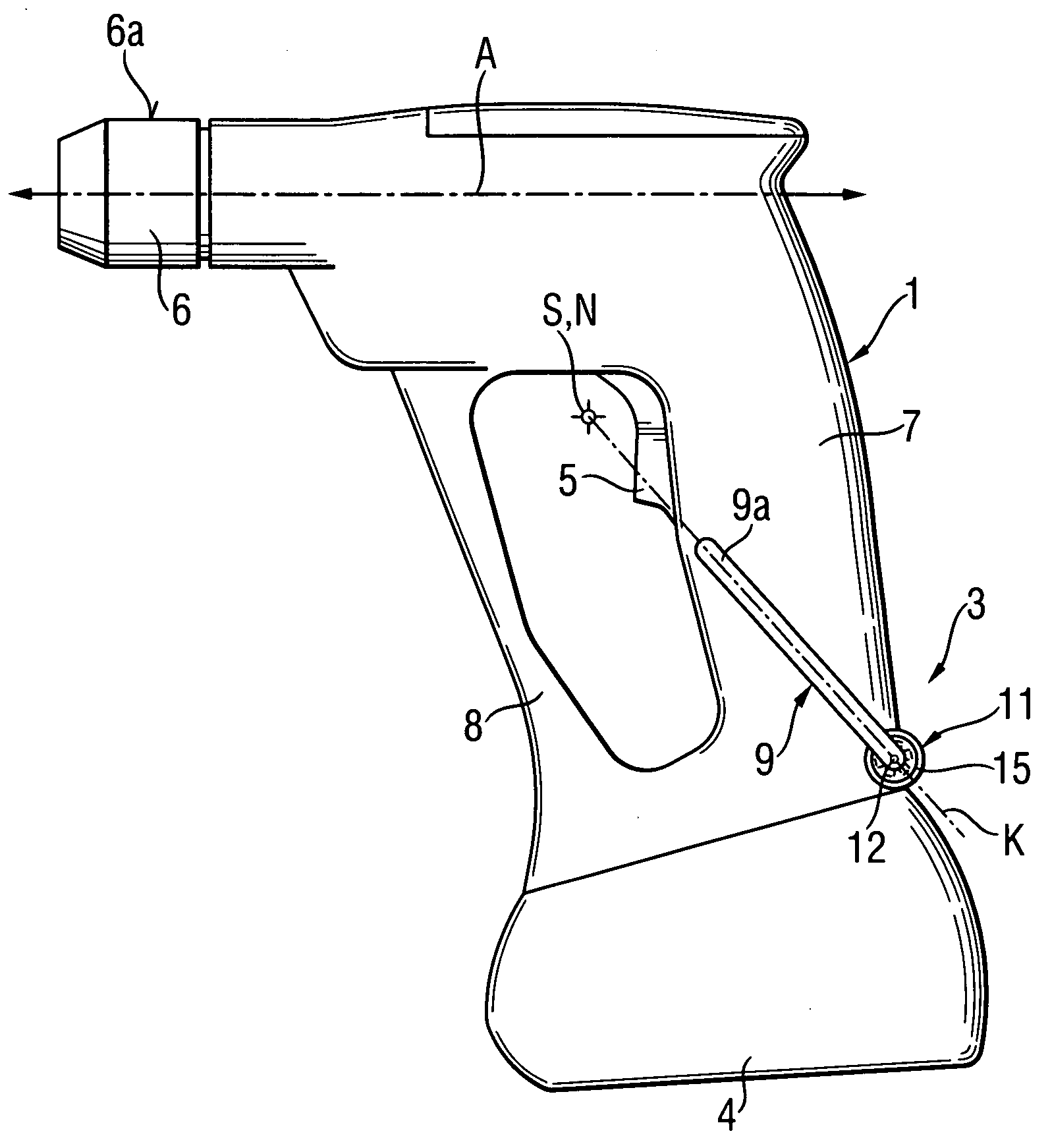
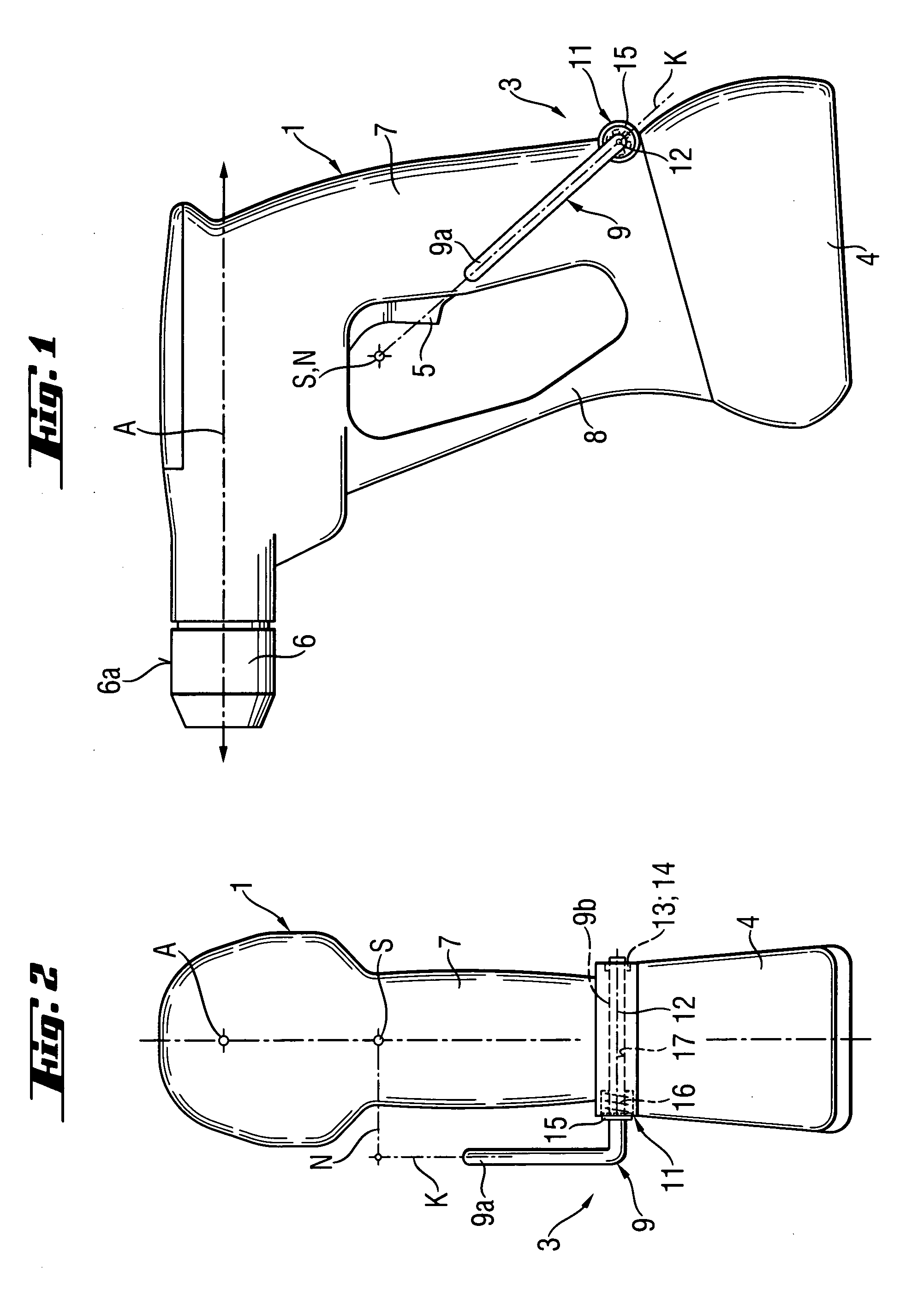
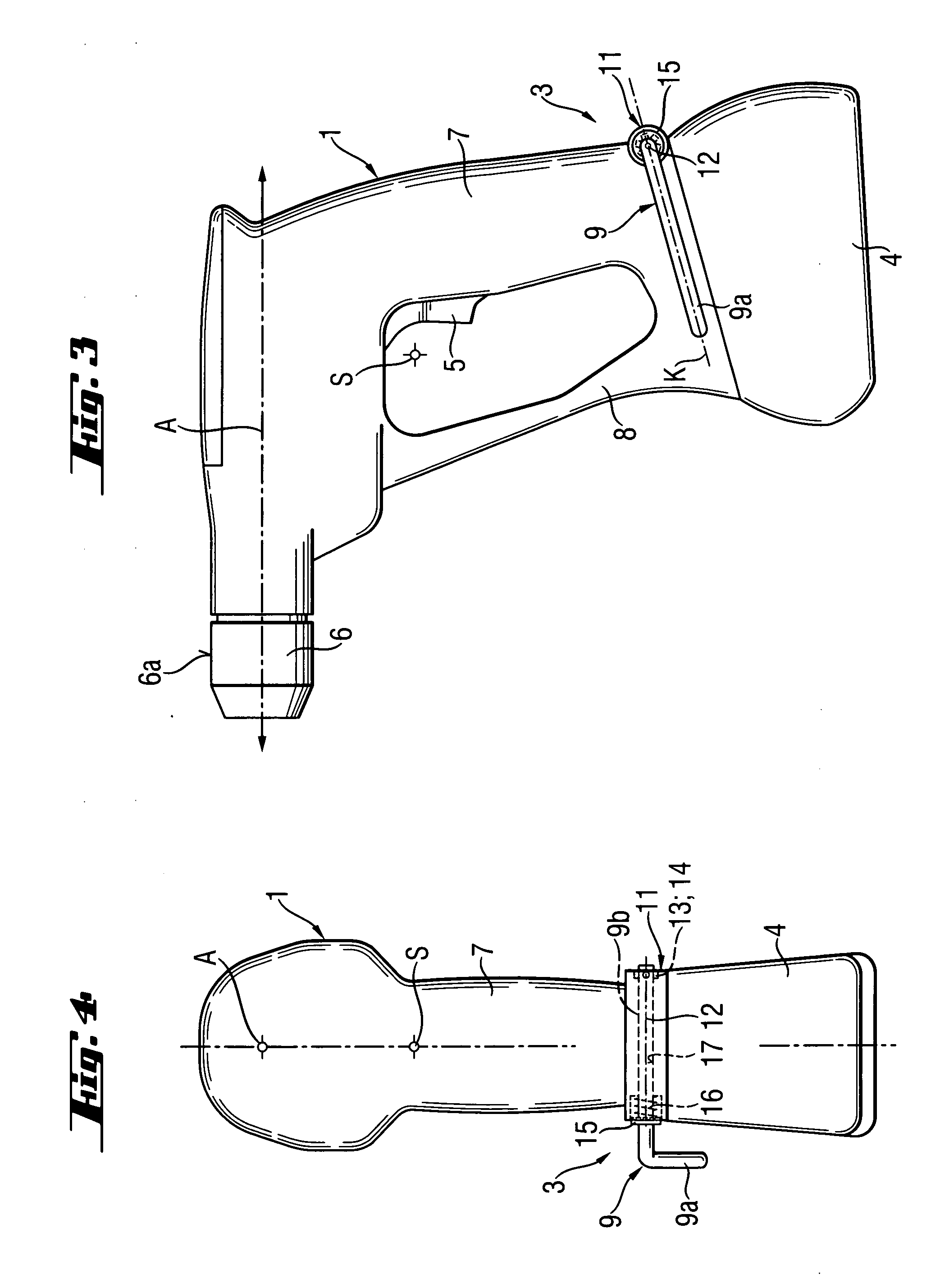
[0027] A hand-held power tool according to the present invention, in particular, a screw driving tool, which is shown in FIGS. 1 through 6, has a housing 1 and at least one holding device 3. For guiding the power tool, the housing 1 has a handle 7 at a free end of which, a rechargeable battery 4 for driving the hand-held power tool is provided.

[0028] In the housing 1, e.g., an electromotor (not shown), which is powered by the battery 4, is located. The electromotor is operatively connected with a drive shaft. The electromotor is turned on and off with a pressure switch 5 provided on the handle 7. The drive shaft is operatively connected with a chuck 6 adjoining the housing 1. The chuck 6 rotates upon actuation of the electromotor. The chuck 6 has a substantially cylindrical outer contour 6a an axis of which coincides with an operational direction A of the hand-held power tool. The substantially cubic rechargeable batter 4 adjoins a free end of the handle 7 and is releasably connect...


PUM

PropertyMeasurementUnit
gravityaaaaaaaaaa
forceaaaaaaaaaa
pressureaaaaaaaaaa

Abstract

A hand-held power tool including a housing (1) having a handle (7), and a holding device (3) having a catch element (9) with a free end (9a) for suspending the power tool, with the free end (9a) having a main axis (K) intersecting a normal live (N) that extends transverse to the tool plane which is defined by the plane of the handle and the operational direction of the tool, and passes through the center of gravity (S) of the tool.

Description

RELATED APPLICATIONS [0001] -This application is a continuation-in-part of patent application Ser. No. 10 / 397,671, filed on Mar. 26, 2003.BACKGROUND OF THE INVENTION [0002] 1. Field of the Invention [0003] The present invention relates to a hand-held power tool having a housing with a handle, and at least one holding device having a catch element with a free end for suspending the power tool. [0004] 2. Description of the Prior Art [0005] Hand-held power tools of the type described above include power tools such as screw driving tools, combustion-engined setting tools, drilling tools, chiseling tools, electrically driven saws, and the like. Often, the hand-held tools have a holding device with a catch element for suspending the tool, e.g., from a belt of a user. The free end of the catch element engages, e.g., a belt, which is tightened on a user, with the tool being suspended from the belt and retained under its own belt. [0006] German Publication DE-4233239 discloses, e.g., a hand-...

Claims


Application Information

Patent Timeline
Patent Type & Authority Applications(United States)
IPC IPC(8): B25F5/02B25H3/00
CPCB25F5/02B25H3/006Y10T16/476Y10T16/4713Y10T16/44Y10T16/498
Inventor BADER, THOMASHOFBRUCKER, THOMASMAHLER, THOMAS
Owner HILTI AG
Why Eureka
Eureka Blog
Learn More