
Dynamically partitioned CAM array

a cam array and dynamic partitioning technology, applied in static storage, information storage, digital storage, etc., can solve the problems of significant power consumption, significant power consumption, and significant power consumption of each row of cam array for each compare operation

Inactive Publication Date: 2010-12-07
AVAGO TECH INT SALES PTE LTD
View PDF39 Cites 54 Cited by
  • Summary
  • Abstract
  • Description
  • Claims
  • Application Information

AI Technical Summary

Benefits of technology

The present invention relates to reducing power consumption in content addressable memories (CAMs) during compare operations. CAMs are used in network switching and routing applications to compare incoming data with stored content addressable words to determine forwarding destinations. However, the process of comparing data with the stored content addressable words consumes significant power. The invention proposes a method and apparatus to reduce power consumption by pre-charging the match lines of the CAM array with the search key, driving the search key onto the comparand lines, and discharging the match lines when a match is found. This reduces power consumption by about half for each compare operation. The invention can be applied to various memory structures and architectures, such as RAM, EPROM, EEPROM, flash memory devices, and TLBs.

Problems solved by technology

Because most of the rows in the CAM array typically mismatch during each compare operation, most of the array's match lines are alternately charged and then discharged during successive compare operations, which results in significant power consumption.
Further, driving the search key to every row of the CAM array for each compare operation also consumes significant power.
Thus, half of all the comparand lines are driven high (e.g., towards VDD) for every compare operation, which consumes significant power.
This undesirable power consumption increases as the number of rows of CAM cells increases, which requires longer comparand lines having greater line capacitances.

Method used


Image

  • Dynamically partitioned CAM array
  • Dynamically partitioned CAM array
  • Dynamically partitioned CAM array

Examples


Embodiment Construction

[0022]A method and apparatus for reducing power consumption in a CAM device is disclosed. It is to be understood that embodiments of the present invention are equally applicable to other memory structures such as, for example, RAM, EPROM, EEPROM, and flash memory devices, as well as other memory architectures including, for example, translation look-aside buffers (TLBs) and look-up tables (LUTs). In the following description, for purposes of explanation, specific nomenclature is set forth to provide a thorough understanding of the present invention. However, it will be apparent to one skilled in the art that these specific details may not be required to practice the present invention. In other instances, well-known circuits and devices are shown in block diagram form to avoid obscuring the present invention unnecessarily. Additionally, the interconnection between circuit elements or blocks may be shown as buses or as single signal lines. Each of the buses may alternatively be a sing...


PUM


Abstract

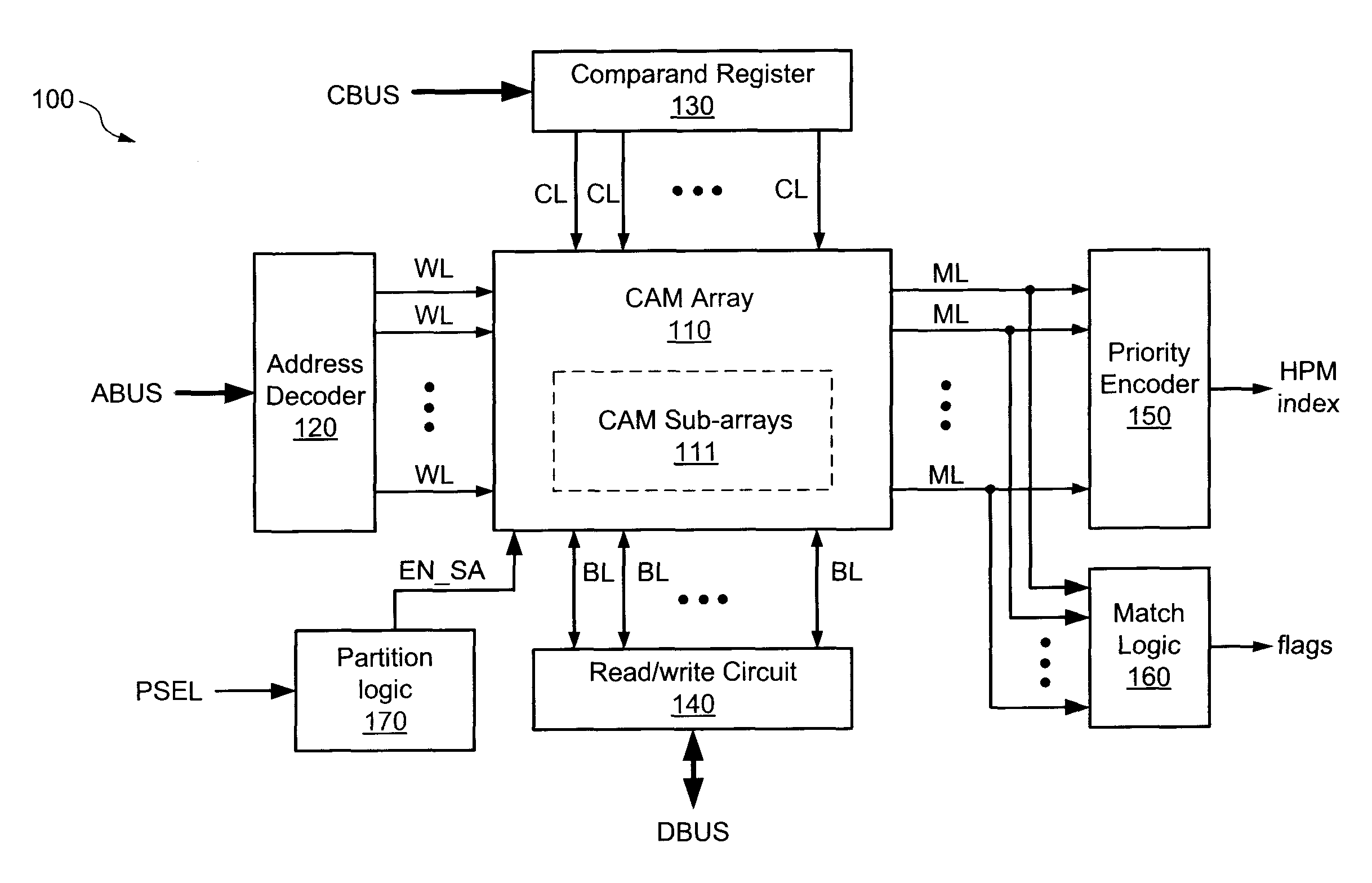
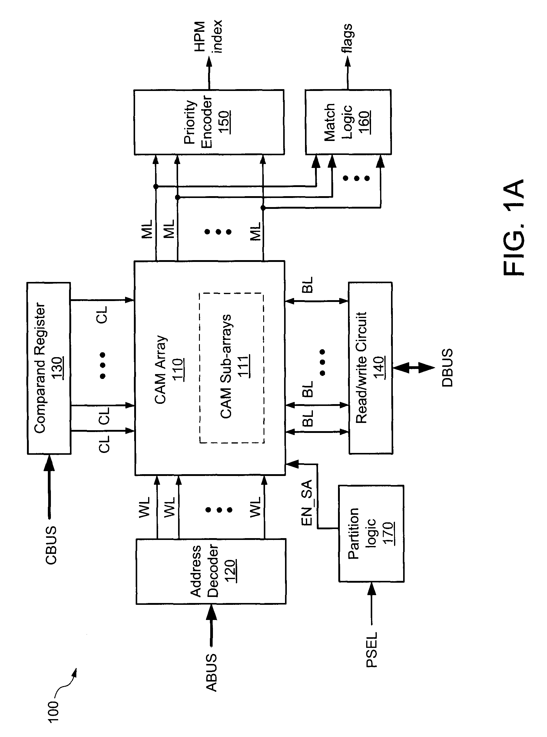
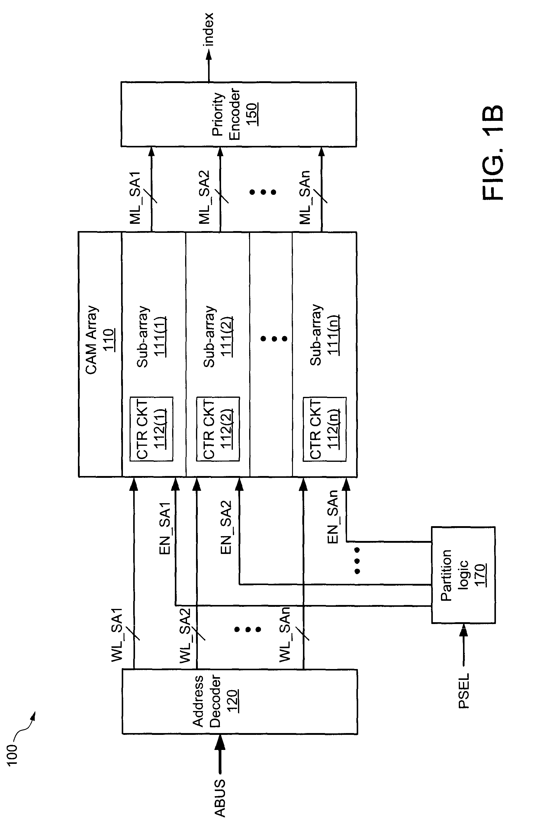
A content addressable memory (CAM) device includes a comparand register, a CAM array, and partition logic. The comparand register has inputs to receive a search key, and outputs coupled to the CAM array, which includes a plurality of individually selectable sub-arrays. Each sub-array includes a number of rows of CAM cells and a control circuit, wherein each row of CAM cells is coupled to a match line, and wherein the control circuit has an input to receive a corresponding sub-array enable signal. The partition logic has an input to receive a partition select signal, and is configured to generate the sub-array enable signals in response to the partition select signal. The control circuits selectively propagate the search key through the sub-arrays in response to the sub-array enable signals.

Description

FIELD OF INVENTION[0001]This invention relates generally to semiconductor memories and specifically to reducing power consumption in content addressable memories.DESCRIPTION OF RELATED ART[0002]Content addressable memory (CAM) devices are frequently used in network switching and routing applications to determine forwarding destinations for data packets. A CAM device can be instructed to compare a selected portion of an incoming packet (e.g., a destination address extracted from the packet header) with CAM words (e.g., forwarding address) stored in an array within the CAM device. If there is a matching entry stored in the CAM array, the index of the matching CAM word can be used to access a corresponding location in an associated memory device to retrieve a destination address and / or other routing information for the packet.[0003]A CAM device includes a CAM array having a plurality of CAM cells organized in a number of rows and columns. Each row of CAM cells, which can be used to sto...

Claims


Application Information

Patent Timeline
Patent Type & Authority Patents(United States)
IPC IPC(8): G11C15/00
CPCG11C15/04
Inventor DESHPANDE, CHETANIYENGAR, VINAYNATARAJ, BINDIGANAVALE S.
Owner AVAGO TECH INT SALES PTE LTD
Learn More