
Security system

a security system and automation technology, applied in the field of security and automation systems, can solve the problems of many false security alarms, few, if any, security devices protecting individual workspaces, and often unmonitored areas, and achieve the effect of effectively eliminating most false security alarms

Inactive Publication Date: 2010-12-07
KIMBALL INTERNATIONAL
View PDF27 Cites 233 Cited by
  • Summary
  • Abstract
  • Description
  • Claims
  • Application Information

AI Technical Summary

Benefits of technology

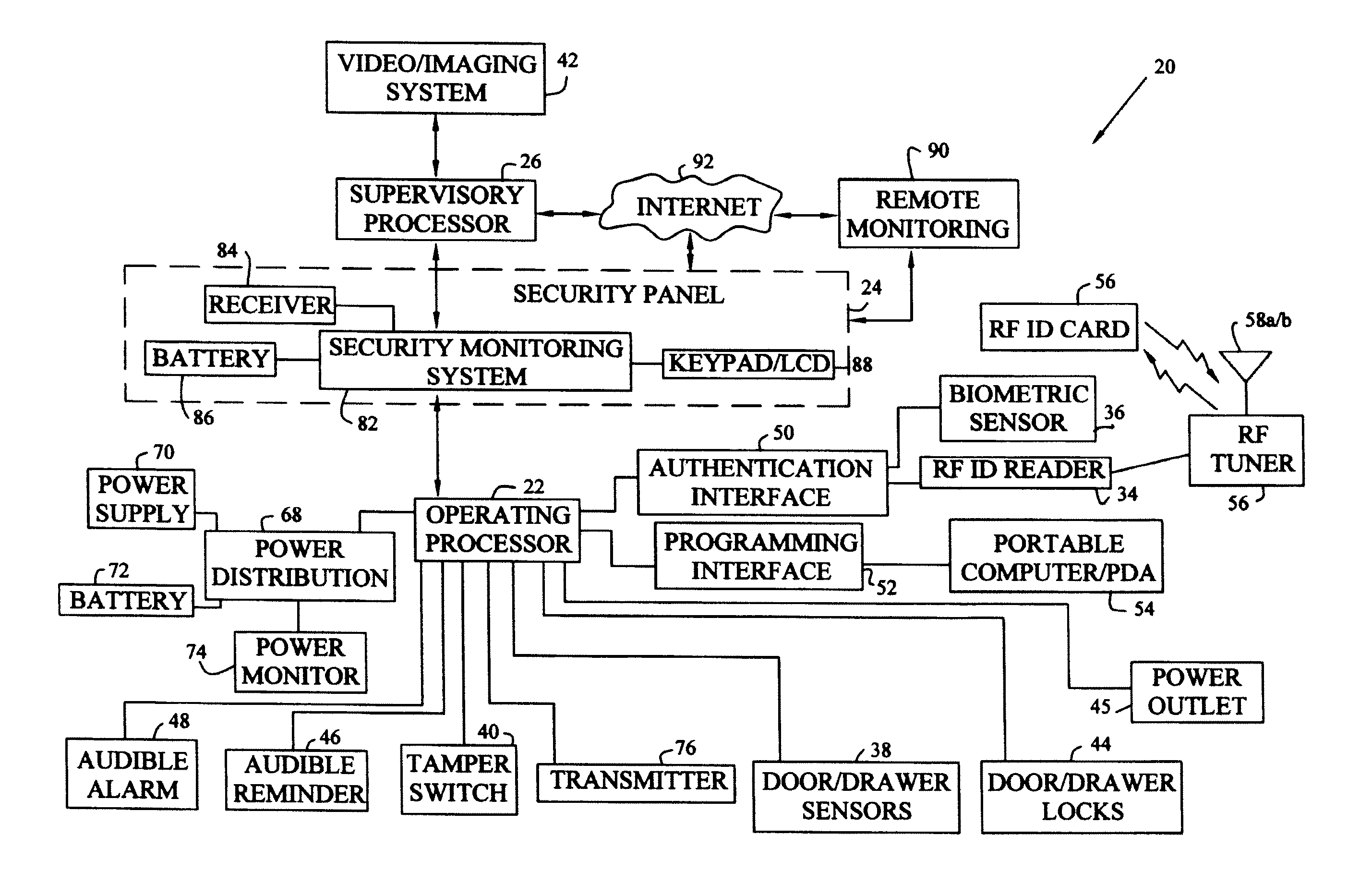
[0013]The system may also include video or imaging surveillance that is controlled and monitored by the supervisory processor and activates storage of images by image-detected motion or by motion detection elements of the operating processor. Additionally, one or more other processors may be interfaced locally or remotely to the supervisory processor. For example, a processor for handling remote alarm response and video surveillance monitoring may be linked via the internet to the supervisory processor. Monitoring of the surveillance system by security personnel can effectively eliminate most false security alarms.

Problems solved by technology

However, once the perimeter of a building or complex is breached, there are generally few, if any, security devices protecting individual workspaces, groups of workspaces, departments, or buildings inside the perimeter.
For example, office components typically have cam locks, which are easily defeated.
Systems typically rely solely on perimeter security while sensitive materials in work areas are often unmonitored and whatever locks exist may be unused.
Even when personnel intend to use locks to secure sensitive areas and materials, mechanical locks cannot warn personnel when the mechanical locks are accidentally left unlocked. locks to secure sensitive areas and materials, mechanical locks cannot warn personnel when the mechanical locks are accidentally left unlocked.
However, outside of controlling manufacturing equipment and production lines, workspace automation is generally limited to environmental controls.
Automation in an office environment is generally nonexistent or limited to environmental controls.

Method used


Image

  • Security system
  • Security system
  • Security system

Examples


first embodiment

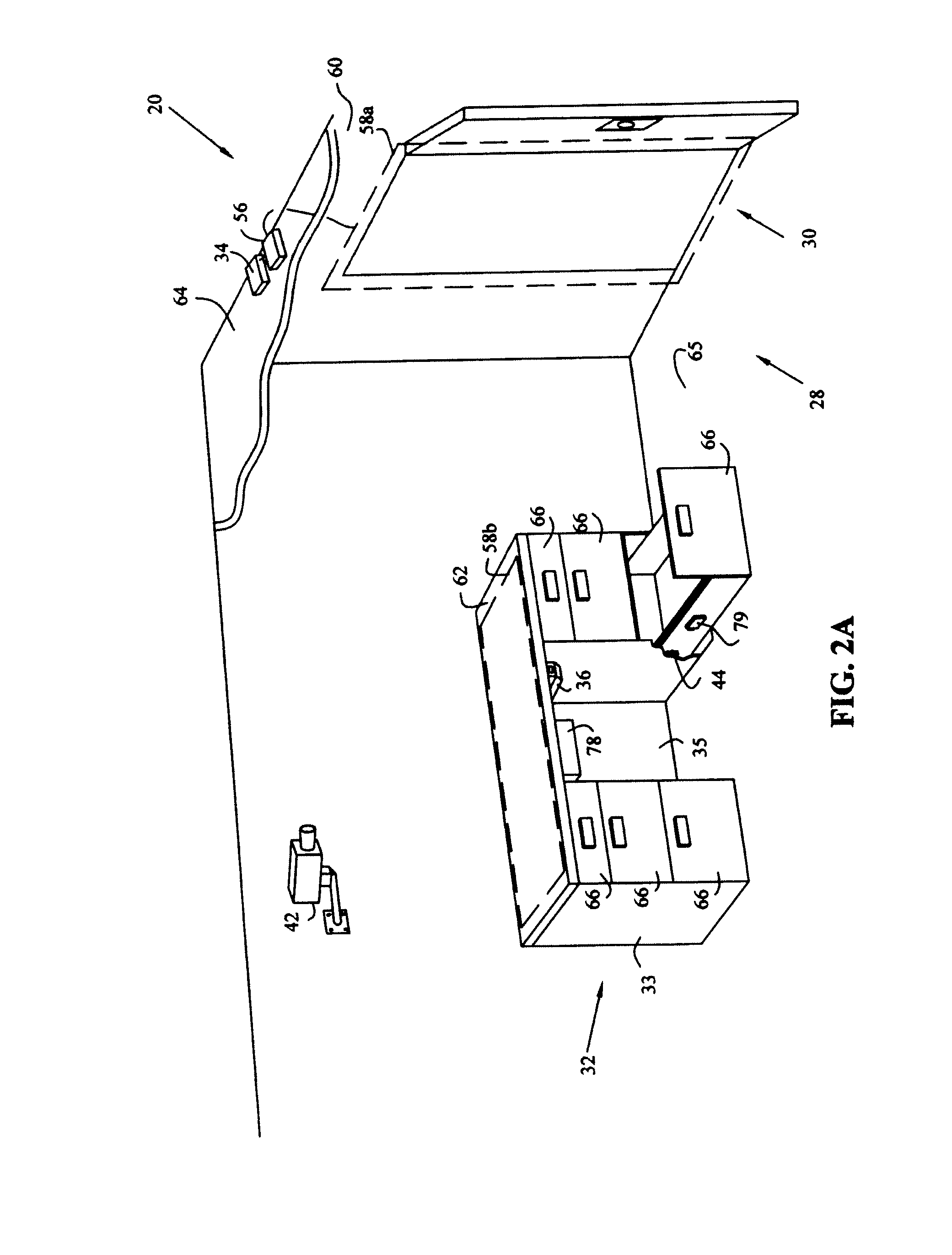
[0063]Although FIG. 2A shows imaging system 42 located within work area 28, alternatively, imaging system 42 could be located outside work area 28 and directed toward entryway 30, thus providing additional privacy for individuals working within work area 28 while monitoring those individuals entering or leaving through entryway 30. Although the first exemplary embodiment of system 20 includes security panel 24 and operating processor 22, alternatively, imaging system 42 and supervisory processor 26 may operate independent of the other components of system 20.

[0064]An exemplary scenario utilizing system 20 shown in FIGS. 1, 2A, and 2B is as follows. As an individual passes through entryway 30 to enter work area 28 containing office furniture component 32, operating processor 22 received an authentication code read by RF ID reader 34 from RF ED card 56 carried by the individual, and using antenna 58a, which is embedded in wall 60 surrounding entryway 30. Reception of an authentication...

second embodiment

[0096]The second exemplary embodiment shown in FIGS. 6-8 and 10 include operating processor 220 having equipment processor 221, environmental processor 223, and voice synthesizer processor 225. Each processor 221, 223 or 225 is dedicated to monitoring, controlling, and automating a specific aspect of the work area. In addition, redundant or backup processors (not shown) also may be directed to the same aspect of the work area. Exemplary processors 221, 223 and 225 for the second embodiment are Model Nos. MM443S, MV480, and MC100, manufactured by ELK Products, Inc.

[0097]Equipment processor 221 receives monitoring device signals from various monitoring devices including, for example, cabinet door sensor 278, drawer sensor 282, and access authentication subprocessor 229. Equipment processor 221 also controls various interconnected devices and systems, including, for example, cabinet door lock 277, drawer lock 281, audible alarm 227, access authentication subprocessor 229, LED indicator...

fourth embodiment

[0103]Referring now to FIG. 12, system 410 is shown, in which operating processors 220a-220e may be located in various work sites in the same or different geographic locations. A particular operating processor such as 220c may be linked to other processors 240 and 250 through network 261. Alternatively, one operating processor 220d or 220e may be interconnected with a supervisory processor 240b or 240c which is in turn interfaced with network 261 or Internet 263. Also, multiple operating processors 220a and 220b may be connected to a single supervisory processor 240a which is in turn connected to network 261 or Internet 263. Supervisory processors 240 monitor and control operating processors 220. Supervisory processors 240 may advantageously include software applications and databases such as Windows-based Savoy Console, and Web-based applications such as Savoy WebEngine, in order to support Internet connection 263. Such software is available from Savoy WebEngines, Inc., of Westboro...


PUM


Abstract

A security system for monitoring, controlling, and automating one or more work areas and office furniture components, or monitoring, controlling, and automating utility components in other environments such as retail, restaurant, and home applications. The system includes passive and active access authentication devices and active or passive unlocking and lockdown devices for utility components, such as storage components, office furniture components, offices, and work sites. The system may include, for example, a processor, an access authentication device, sensors for monitoring work areas, actuators for controlling and automating work areas, and status and alarm notifiers.

Description

CROSS REFERENCE TO RELATED APPLICATIONS[0001]This application is a continuation-in-part of U.S. patent application Ser. No. 10 / 376,842, entitled WORKSPACE SECURITY SYSTEM, filed on Feb. 28, 2003, now U.S. Pat. No. 6,965,294, which claims the benefit under Title 35, U.S.C. §119(e) of U.S. Provisional Patent Application Ser. No. 60 / 360,554, entitled WORKSPACE MONITORING, CONTROL, AND AUTOMATION SYSTEM, filed on Feb. 28, 2002.BACKGROUND OF THE INVENTION[0002]1. Field of the Invention[0003]The present invention relates to security and automation systems, and in particular to a system for monitoring, controlling, and automating workspaces and office furniture components in multiple offices and facilities, as well as to systems for monitoring, controlling, and automating utility components in other environments, such as retail, restaurant, and home environments.[0004]2. Description of the Related Art[0005]Existing security systems are commonly used to secure the perimeter of a building or...

Claims


Application Information

Patent Timeline
IPC IPC(8): G06K19/00G08B13/00
CPCG07C9/00896G08B13/2402G08B13/2491G07C9/00563G07C2209/65
Inventor THYEN, CHRIS JELLIOTT, BRENTFENWICK, JEFF
Owner KIMBALL INTERNATIONAL
Learn More