
System and inlet device for separating a mixture

a technology of system and inlet device, which is applied in the direction of auxillary pretreatment, liquid displacement, separation process, etc., can solve the problems of large amount of liquid being lifted upwards, liquid overloading any second stage separation unit installed, and the type of cyclonic inlet device cannot be used, so as to improve the separation

Active Publication Date: 2010-11-16
FMC TECH CV
View PDF27 Cites 27 Cited by
  • Summary
  • Abstract
  • Description
  • Claims
  • Application Information

AI Technical Summary

Benefits of technology

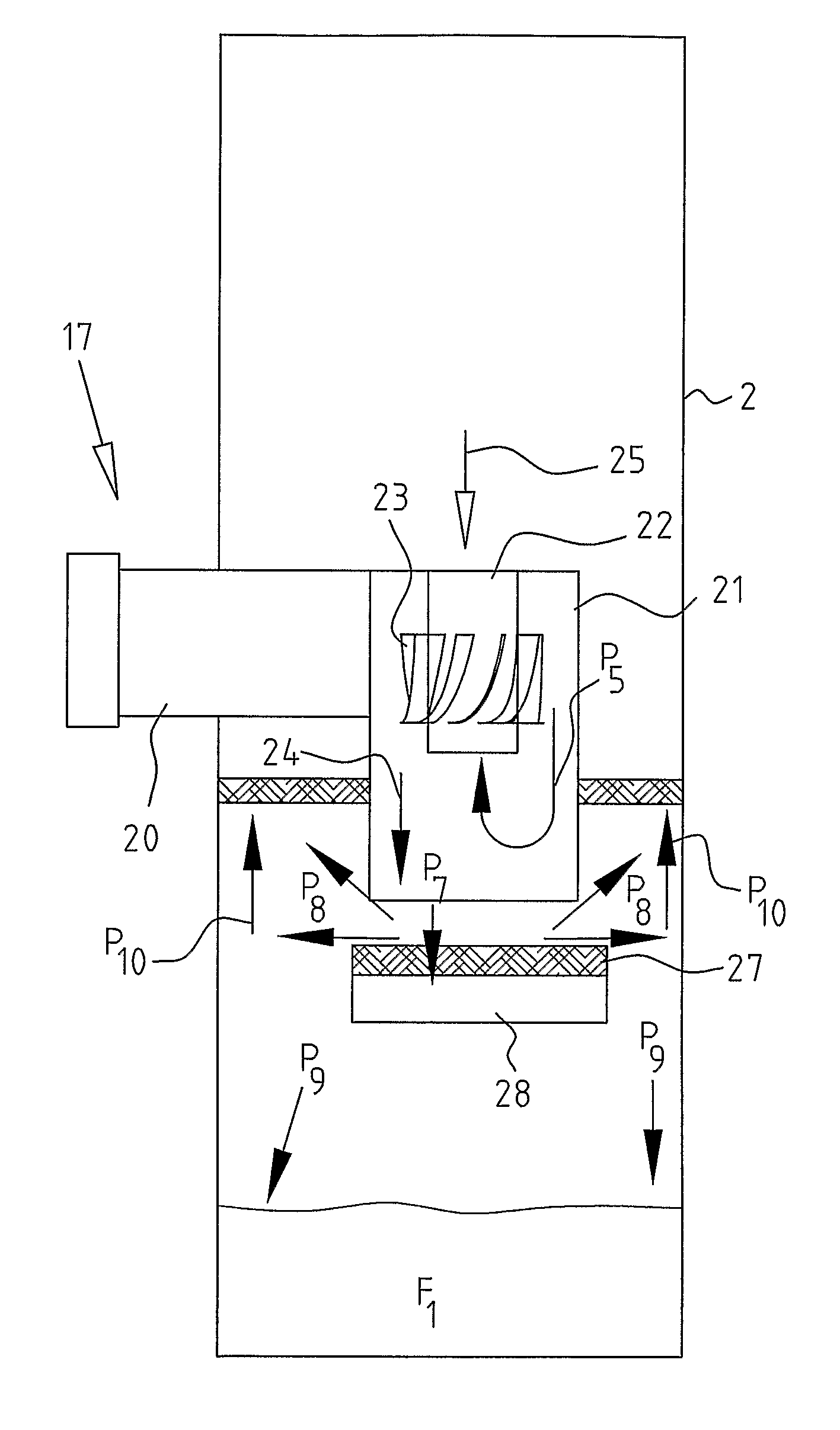
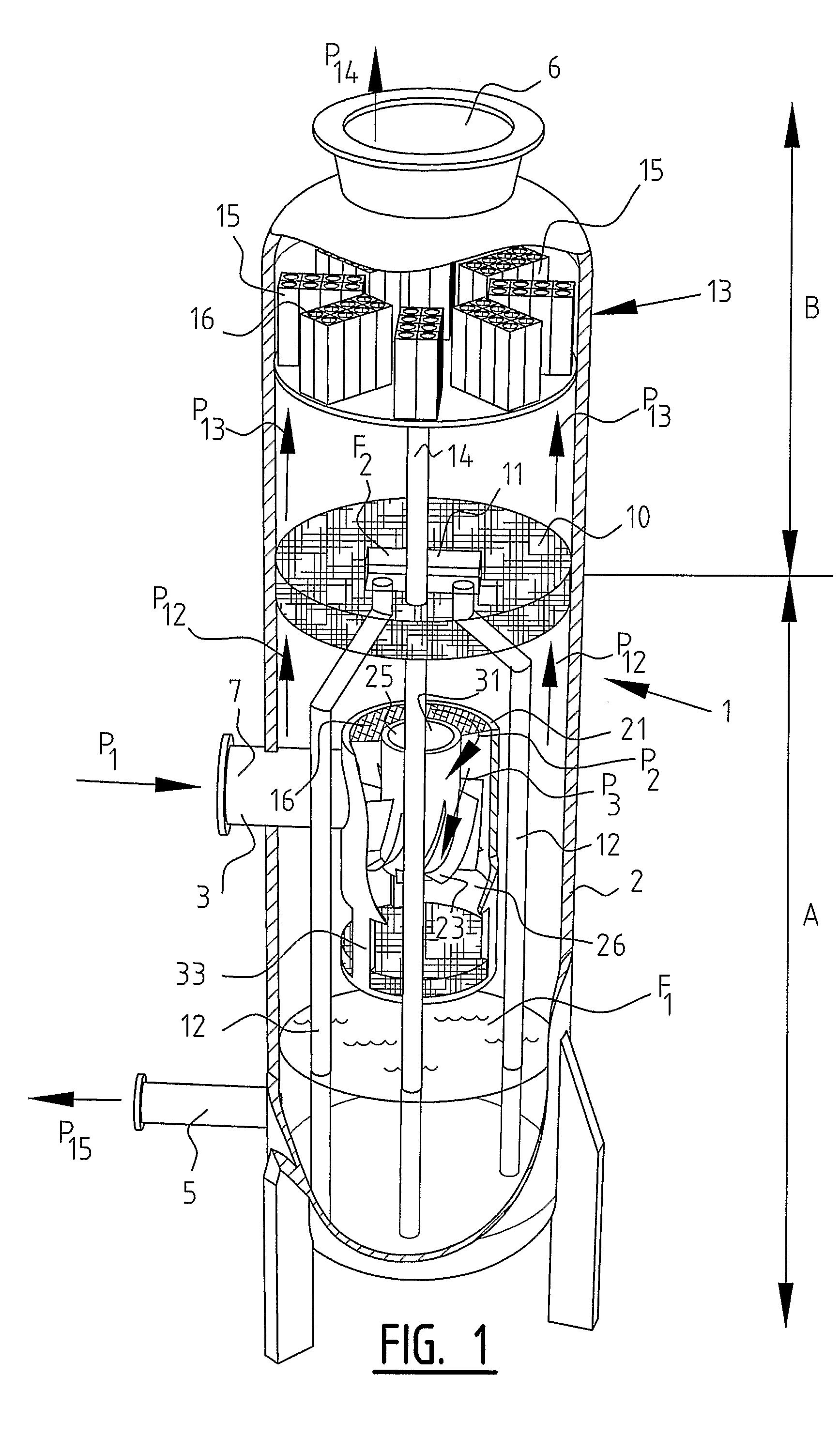
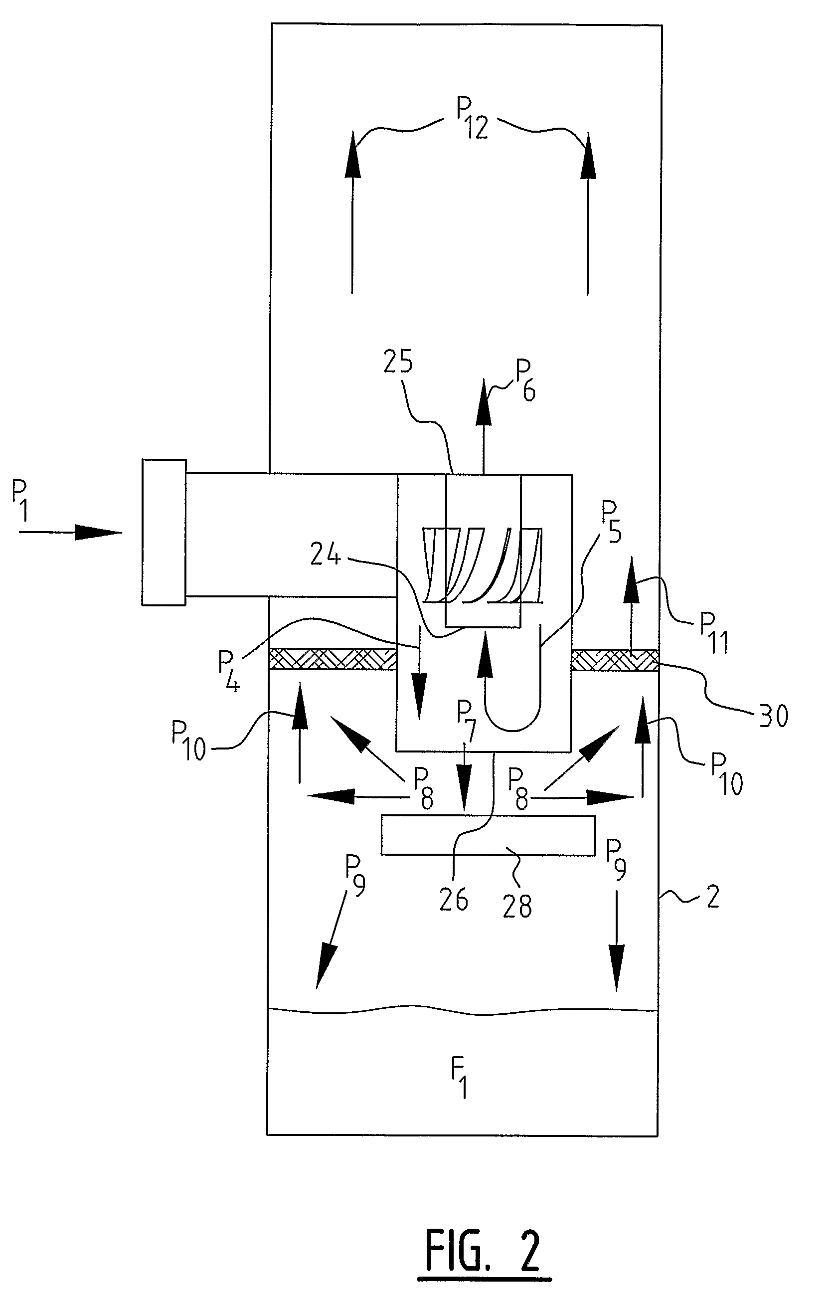
[0023]In one embodiment, the inlet device may also comprise a momentum breaker arranged below the liquid outlet of the casing so as to at least partially absorb the momentum of the first mixture part, and a demister element positioned upstream of the momentum breaker. The momentum breaker, for instance a plate-like element extending perpendicular to the relatively heavy mixture part flowing from the lower outlet of the inlet device, the plate being arranged below the liquid outlet, prevents the gas / liquid mixture to splash into the liquid sump in the lower compartment of the vessel. This reduces the amount of liquid that may be entrained by the gas / liquid mixture from the liquid surface. The separation efficiency may be improved even further by providing the at least one demister element. The momentum of the liquid / gas mixture leaving the cyclone outlet will then be partially absorbed at the same time as it will drain the liquid. Liquid is typically seen draining into the lower compartment of the separator through the lower part of the demister element. The gas changes direction and moves upwards. The effect is a further improvement of the overall separation efficiency of the inlet device.
[0038]Especially good results, however, may be obtainable in a further embodiment wherein the separation means comprise one or more third demister elements (second stage), for example, one or more agglomerators / coalescers, for instance in an upright vessel extending substantially horizontally over substantially the entire cross-section of the vessel. Alternatively or additionally, the separation results may be improved when the system comprises, at a position between the upper vessel outlet and the inlet device, one or more axial cyclones, preferably recycle cyclones, for further separation of the mixture.

Problems solved by technology

In applications where the available static head of liquid is too short, these kind of cyclonic inlet devices could not be used.
This is because, if gas breaks through at the bottom of the cyclone, there is a possibility that large amounts of liquid are lifted upwards as the gas enters the liquid surrounding the cyclone.
This liquid may in turn overload any second stage separation unit installed downstream of the inlet cyclone.
If an inlet cyclone were to be installed that is not (partially) submerged in the liquid in the lower compartment, then the following problems may arise.
In some circumstances, too much gas escapes out of the liquid outlet of the inlet cyclone.
Also, the amount of gas leaving the bottom liquid outlet may be so large that it will interfere with the liquid surface.
This may cause liquid to be entrained from the liquid surface, which causes the separation efficiency to deteriorate.
Another problem is that gas from the interior of the separation vessel may be sucked into the inlet cyclone through the liquid outlet of the cyclone.
If gas is sucked into the inlet cyclone through the liquid outlet, this will block the liquid from being discharged properly.
This is the worst scenario as the separation efficiency of liquid becomes practically zero.

Method used


Image

  • System and inlet device for separating a mixture
  • System and inlet device for separating a mixture
  • System and inlet device for separating a mixture

Examples


Embodiment Construction

[0047]Illustrative embodiments of the present subject matter are described below. In the interest of clarity, not all features of an actual implementation are described in this specification. It will of course be appreciated that in the development of any such actual embodiment, numerous implementation-specific decisions must be made to achieve the developers' specific goals, such as compliance with system-related and business-related constraints, which will vary from one implementation to another. Moreover, it will be appreciated that such a development effort might be complex and time-consuming, but would nevertheless be a routine undertaking for those of ordinary skill in the art having the benefit of this disclosure.

[0048]The present subject matter will now be described with reference to the attached figures. The words and phrases used herein should be understood and interpreted to have a meaning consistent with the understanding of those words and phrases by those skilled in th...


PUM

PropertyMeasurementUnit
distanceaaaaaaaaaa
thicknessaaaaaaaaaa
momentumaaaaaaaaaa

Abstract

The invention relates to a system for separating a mixture of gas and liquid into a heavy fraction and a light fraction, the system comprising:—a separation vessel having a vessel inlet for the supply of the mixture to be separated, an upper vessel outlet for the discharge of the light fraction and a lower vessel outlet for the discharge of the heavy fraction;—at least one inlet device for pretreatment of the incoming mixture, the inlet device, comprising a casing having a liquid outlet for the discharge of a first mixture part mainly containing liquid to a lower compartment of the separation vessel; and at least one demister element arranged at a position below the liquid outlet for separating liquid from the gas in the first mixture part flowing from the liquid output.

Description

BACKGROUND OF THE INVENTION[0001]1. Field of the Invention[0002]The present disclosure relates to a system for separating a mixture of at least one gas and at least one liquid into a heavy fraction mainly containing liquid and a light fraction mainly containing gas. The disclosure also relates to an inlet device for pretreatment of a mixture of at least one gas and at least one liquid to be separated into a heavy fraction and a light fraction.[0003]2. Description of the Related Art[0004]In the oil and gas industry, separators are known for separating the supplied mixture of liquid (oil and / or water) and gas into a stream of substantially gas and a stream of substantially liquid. Numerous separators are known for separating such gas / liquid mixtures.[0005]Known from WO 03 / 074156 A1 is a separator consisting of an upright column (upright vessel) provided with an inlet for the mixture to be separated and a first and second outlet for the discharge of, respectively, the separated heavy f...

Claims


Application Information

Patent Timeline
Patent Type & Authority Patents(United States)
IPC IPC(8): B01D50/00
CPCB01D45/12B04C5/103B04C5/181B04C5/02B04C5/08B04C5/28
Inventor LARNHOLM, PER-REIDARSCHOOK, ROBERT
Owner FMC TECH CV
Learn More