
Chassis structure for mid-wheel drive power wheelchair

a power wheelchair and chassis technology, applied in the direction of pedestrian/occupant safety arrangements, vehicular safety arrangements, tractors, etc., can solve the problems of minus vibration of the wheelchair and rider discomfort, and achieve the best shock absorption

Inactive Publication Date: 2010-11-09
KARMA MEDICAL PRODUCTS CO LTD
View PDF10 Cites 65 Cited by
  • Summary
  • Abstract
  • Description
  • Claims
  • Application Information

AI Technical Summary

Benefits of technology

[0015]It is the primary objective of the present invention to provide a chassis structure for a mid-wheel drive power wheelchair, which has the best shock absorbing effect when running on a depression or on a bump.
[0016]It is another objective of the present invention to provide a chassis structure for a mid-wheel drive power wheelchair, which uses the press cylinders to maintain the front wheels and the rear wheels contact with the ground so that the wheelchair rolls in a steady status.
[0017]It is a further objective of the present invention to provide a chassis structure for a mid-wheel drive power wheelchair, which maintains the frame in a balancing and steady status.

Problems solved by technology

Thus, the first elastic member D4 and the second elastic member D5 can not react in a first response and the wheelchair will have a minus vibration, which makes the rider uncomfortable.

Method used


Image

  • Chassis structure for mid-wheel drive power wheelchair
  • Chassis structure for mid-wheel drive power wheelchair
  • Chassis structure for mid-wheel drive power wheelchair

Examples


Embodiment Construction

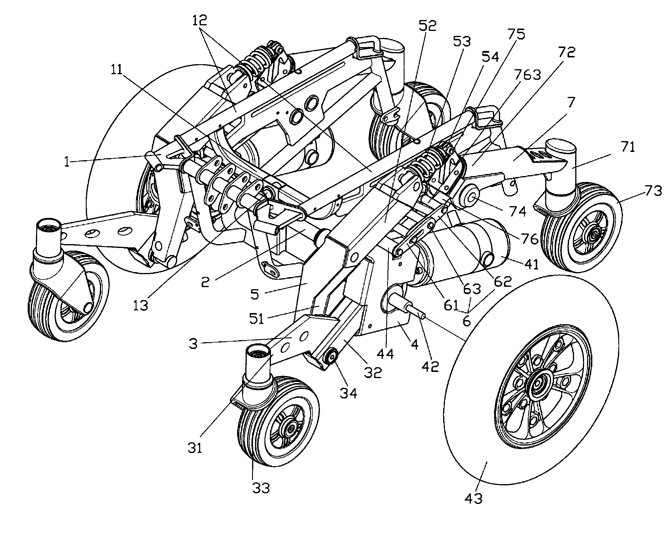
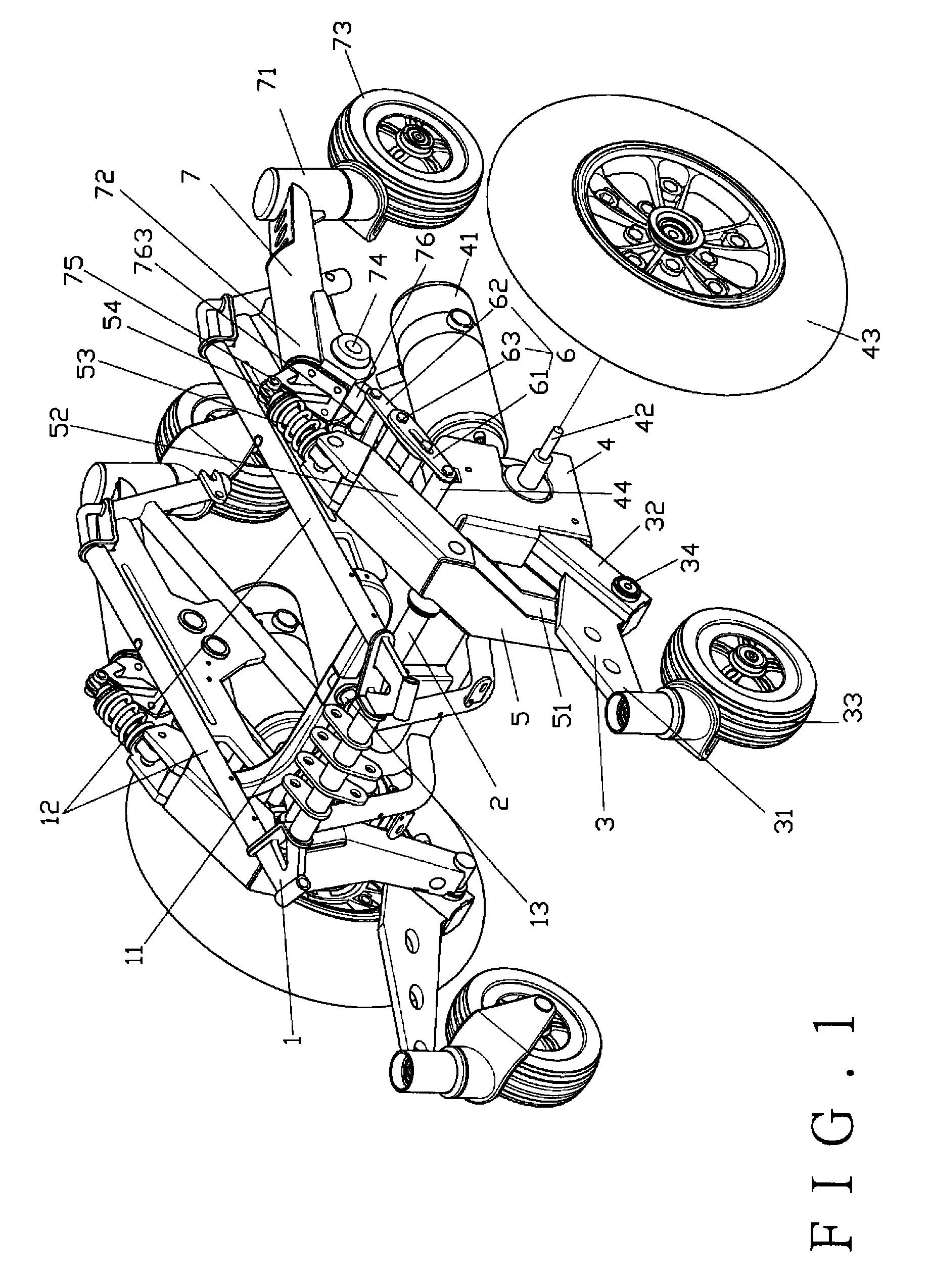
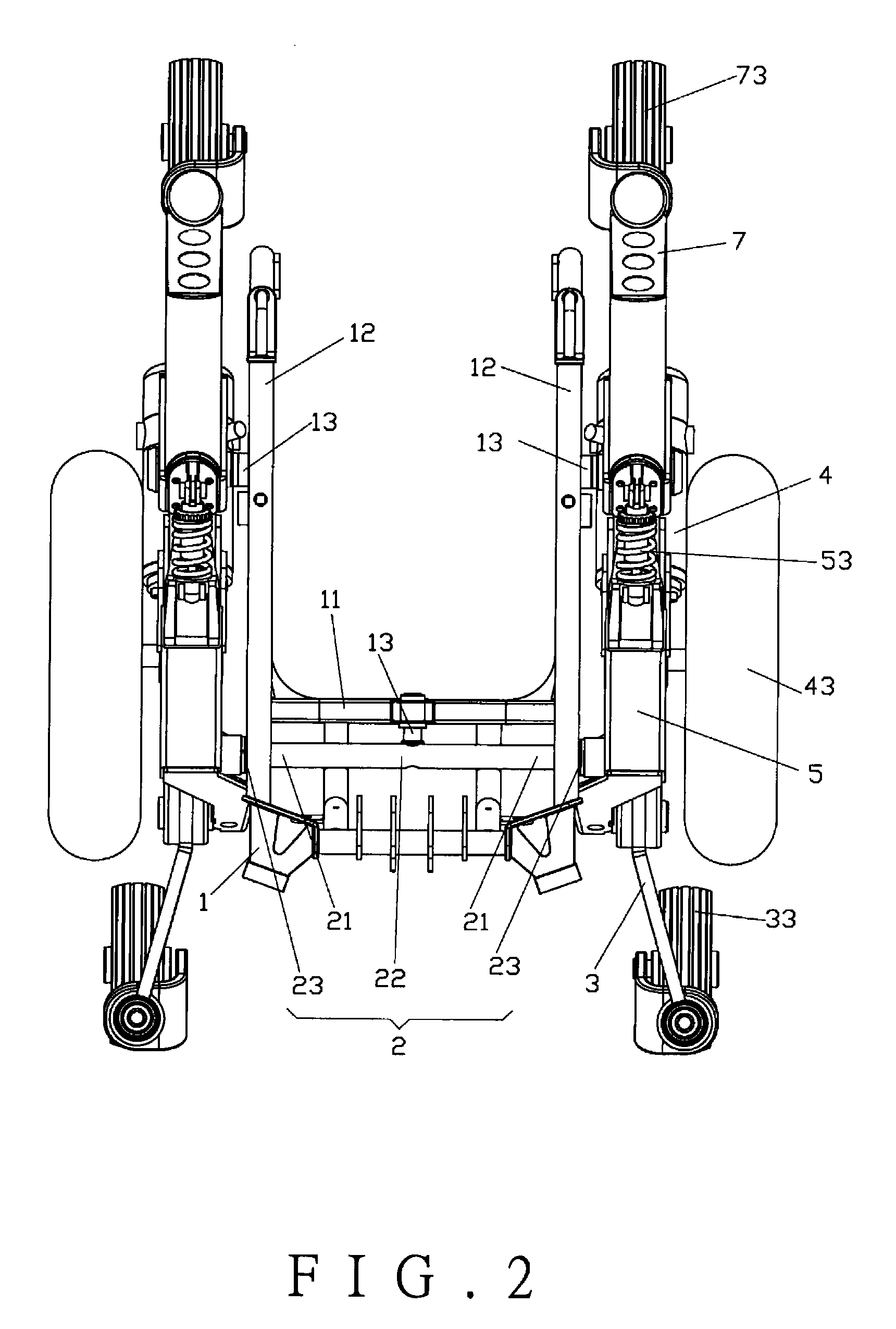
[0030]As shown in FIGS. 1, 2, and 3, a chassis structure for a mid-wheel drive power wheelchair of the present invention comprises a frame 1, a transverse pipe 2, a pair of front wheel rods 3, a pair of driving units 4, a pair of connecting racks 5, a pair of restricting racks 6, and a pair of rear wheel rods 7.

[0031]The frame 1 comprises a front section 11, two side sections 12, and three connecting rods 13 connected to the front section 11 and the two side sections 12, respectively.

[0032]The transverse pipe 2 has two ends 21 and a middle section 22 between the two ends 21. The middle section 22 is pivotally connected to the connecting rod 13 on the front section 11 of the frame 1. The two ends 21 of the transverse pipe 2 are covered with rubber sleeves 23.

[0033]Each front wheel rod 3 has a first end 31, a second end 32 and a first connecting portion 34 between the first end 31 and the second end 32. The first end 31 is connected to a front wheel 33.

[0034]Each driving unit 4 is sec...


PUM


Abstract

A chassis structure for a mid-wheel drive power wheelchair includes a pair of restricting racks each having a first restricting plate and a second restricting plate. Each restricting plate has a slot at a central portion thereof. A first fixing member is inserted through one end of the first restricting plate and the slot of the second restricting plate, and a second fixing member is inserted through one end of the second restricting plate and the slot of the first restricting plate, so that the two restricting plates overlap to extend and restrict with each other for maintaining a steady and balancing ride.

Description

BACKGROUND OF THE INVENTION[0001]1. Field of the Invention[0002]The present invention relates to a chassis structure for a mid-wheel drive power wheelchair, and more particularly to one that uses a restricting rack having a slot to absorb a slight drop height of a front wheel rod, a driving unit and a rear wheel rod and to maintain a balancing of wheels.[0003]2. Description of the Prior Art[0004]Wheelchairs are necessity to the elderly and some disabled people for their daily life. As shown in FIG. 11, a conventional chassis structure for a mid-wheel drive power wheelchair comprises a frame A, a front wheel unit B, a driving unit C, a shock absorber unit D and a rear wheel unit E. The shock absorber unit D is pivotally connected to the frame A. The shock absorber unit D comprises a rod D1 and a block D2 at a central section thereof. The block D2 has a first end D21 and a second end D22. The block D2 is secured to the frame A. The first end D21 of the block D2 is provided with a firs...

Claims


Application Information

Patent Timeline
Patent Type & Authority Patents(United States)
IPC IPC(8): B62M1/14
CPCA61G5/043A61G5/063A61G2005/1078Y10S180/907A61G5/1078
Inventor VREESWIJK, WILHELMUS HENDRIKUS JOHANNES ADRIANAROYCROFT, LAWRENCE WILLIAM ANTHONY
Owner KARMA MEDICAL PRODUCTS CO LTD
Learn More