
Addressing method and method and apparatus for establishing host identity protocol (HIP) connections between legacy and HIP nodes

a technology of host identity protocol and socket node, which is applied in the direction of data switching network, wireless communication, instruments, etc., can solve the problems of increasing complexity, affecting the security of the network,

Inactive Publication Date: 2010-11-02
TELEFON AB LM ERICSSON (PUBL)
View PDF9 Cites 11 Cited by
  • Summary
  • Abstract
  • Description
  • Claims
  • Application Information

AI Technical Summary

Benefits of technology

HIP enables secure and stable mobility management and multi-homing by separating identity and location functions, allowing for secure communication between HIP-enabled and non-HIP enabled hosts through a HIP proxy, which maintains a mapping for secure connection establishment and routing.

Problems solved by technology

There was little need to consider techniques for dealing with host mobility since computers were relatively bulky and immobile.
However, experience has shown that it is fairly hard to reach combined security and mobility using the current standards.
When mobility is also considered, the situation becomes even more complicated: since IP addresses act as host identifiers in this scheme, they must not be changed, however, since IP addresses also describe topological locations, they must necessarily change when a host changes its location in the network.
Clearly, it is impossible to achieve both stability and dynamic changes at the same time.
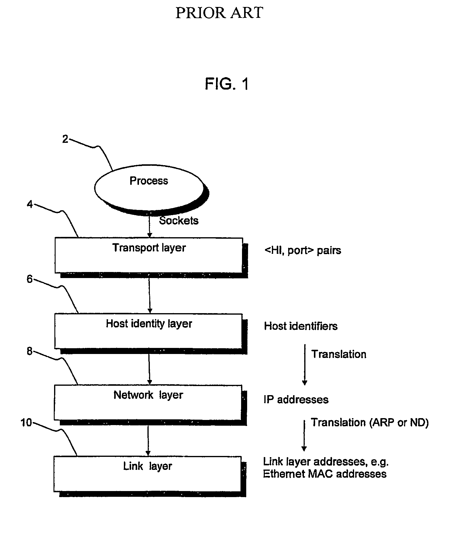
The HIP Host Identity (HI), being a public key, can be quite long and is therefore not practical in all situations.
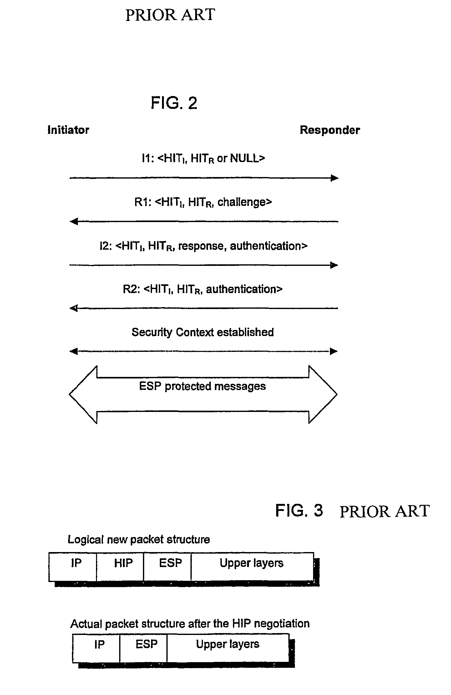
If, for some reason, the packet is routed to a wrong destination, the receiver is not able to open the packet as it does not have the correct key.
The DNS system is too slow to be used for constantly changing location information.
False, or non-routable, addresses in the REA packet may be caused either because the HMN is a malicious node, it has an error in the stack implementation, or the HMN may be inside a network that uses private addresses that are not routable in the Internet.

Method used


Image

  • Addressing method and method and apparatus for establishing host identity protocol (HIP) connections between legacy and HIP nodes
  • Addressing method and method and apparatus for establishing host identity protocol (HIP) connections between legacy and HIP nodes
  • Addressing method and method and apparatus for establishing host identity protocol (HIP) connections between legacy and HIP nodes

Examples


Embodiment Construction

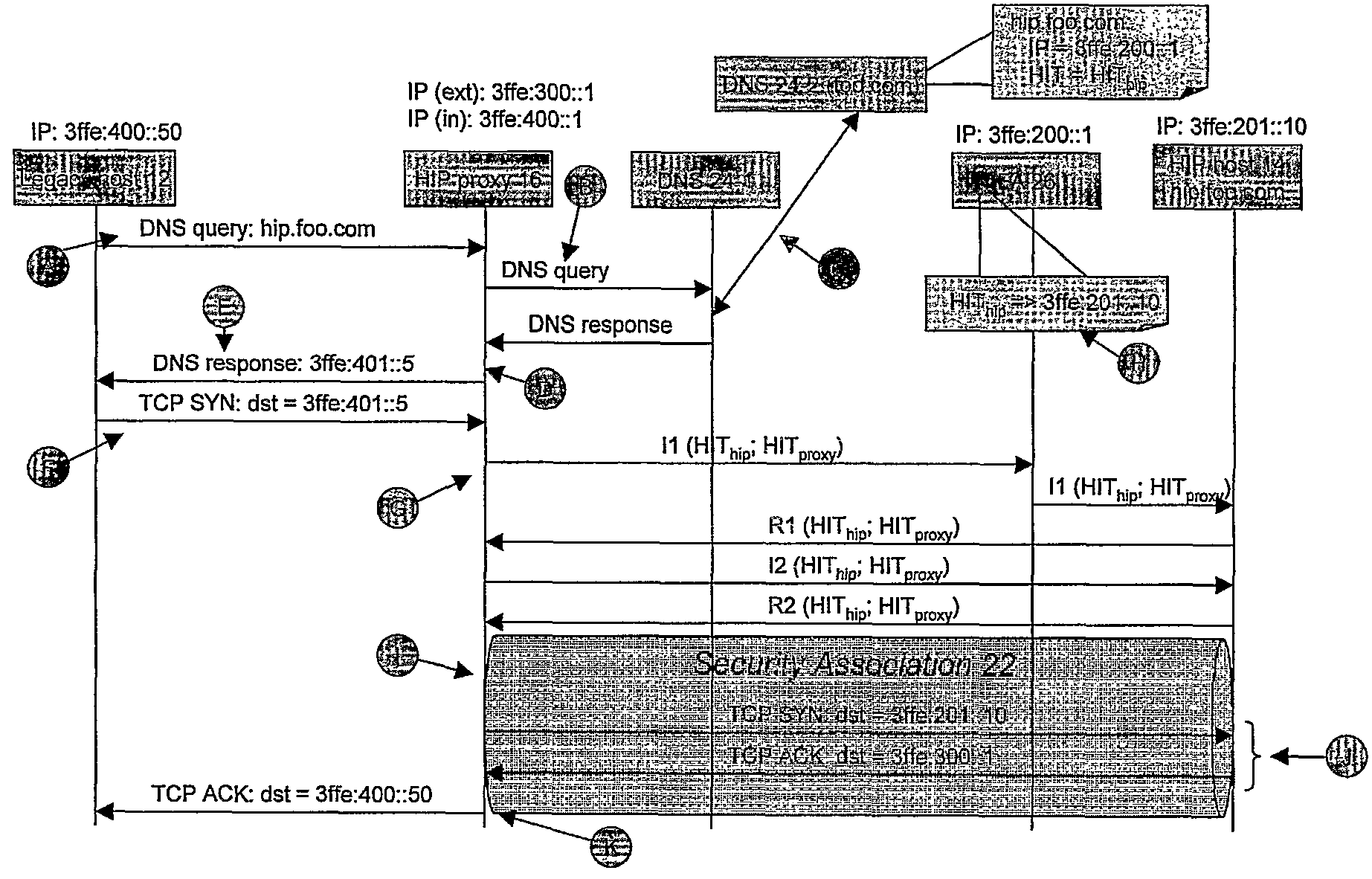
[0076]An embodiment of the present invention will now be described within the general framework of the system described above with reference to FIG. 5. An embodiment of the present invention provides a method of at least partially securing communications between the legacy host 12, which is not HIP enabled, and the HIP host 14, which is HIP enabled via the HP proxy 16 (also referred to as “proxy” (also referred to as “HIP node”) and “HIP proxy node”). Operation of an embodiment of the present invention will now be described with reference to the message exchange diagram of FIG. 6. The steps shown in FIG. 6 are also illustrated in more detail in FIGS. 8 to 12, while FIG. 7 gives a more detailed overview of the packet structures used in TCP, UDP (User Datagram Protocol), ESP and HIP.

[0077]Consider the situation where the legacy host 12 wishes to initiate communication between itself and the HIP host 14. The legacy host 12 knows the domain name of the HIP host 14 to be “hip.foo.com”, a...


PUM


Abstract

A method is provided of at least partially securing communications, via a HIP proxy (16), between a first host (12) which is not HIP enabled and a second host (14) which is HIP enabled, the method comprising: sending (A) a query from the first host (12) to resolve the IP address of the second host (14); in response to said query, retrieving (B, C) an IP address (IPfa) and HIT (HIThip) associated with the second host (14), returning (E) from the proxy (16) a substitute IP address (IPres) associated with the second host (14), and maintaining (D) at the proxy (16) a mapping between the substitute IP address (IPres), the retrieved IP address (IPfa) and the retrieved HIT (HIThip); and upon receipt (F) of a session initiation message (TCP SYN) at the proxy (16) from the first host (12) including as its destination address the substitute IP address (IPres), using the mapping to negotiate a secure HIP connection (22) between the proxy (16) and the second host (14).

Description

[0001]This application is the US national phase of international application PCT / EP2004 / 050129, filed 13 Feb. 2004, which designated the U.S., the entire content of which is hereby incorporated by reference.BACKGROUND OF THE INVENTION[0002]1. Field of the Invention[0003]The present invention relates to a method of at least partially securing communications between a host which is not HIP enabled and another host which is HIP enabled. The present invention also relates to a communications system and HIP proxy using such a method.[0004]2. Description of the Related Art[0005]When the Internet was originally devised, hosts were fixed in location and there was implicit trust between users despite the lack of real security or host identification protocols, and this situation continued even upon wider uptake and use of the technology. There was little need to consider techniques for dealing with host mobility since computers were relatively bulky and immobile.[0006]With the revolution in t...

Claims


Application Information

Patent Timeline
Patent Type & Authority Patents(United States)
IPC IPC(8): G06F15/16H04L9/32H04B1/26H04L12/56H04L29/06H04L29/08H04L29/12H04W8/26H04W80/04
CPCH04L29/12009H04L29/12018H04L61/10H04L63/0281H04L63/0428H04L69/163H04W8/26H04W80/04H04L69/16H04L61/00
Inventor SALMELA, PATRIKWALL, JORMAJOKELA, PETRI
Owner TELEFON AB LM ERICSSON (PUBL)
Learn More