
Method and apparatus for direct digital to radio frequency conversion

Inactive Publication Date: 2010-11-02
GOOGLE TECH HLDG LLC
View PDF15 Cites 20 Cited by
  • Summary
  • Abstract
  • Description
  • Claims
  • Application Information

AI Technical Summary

Problems solved by technology

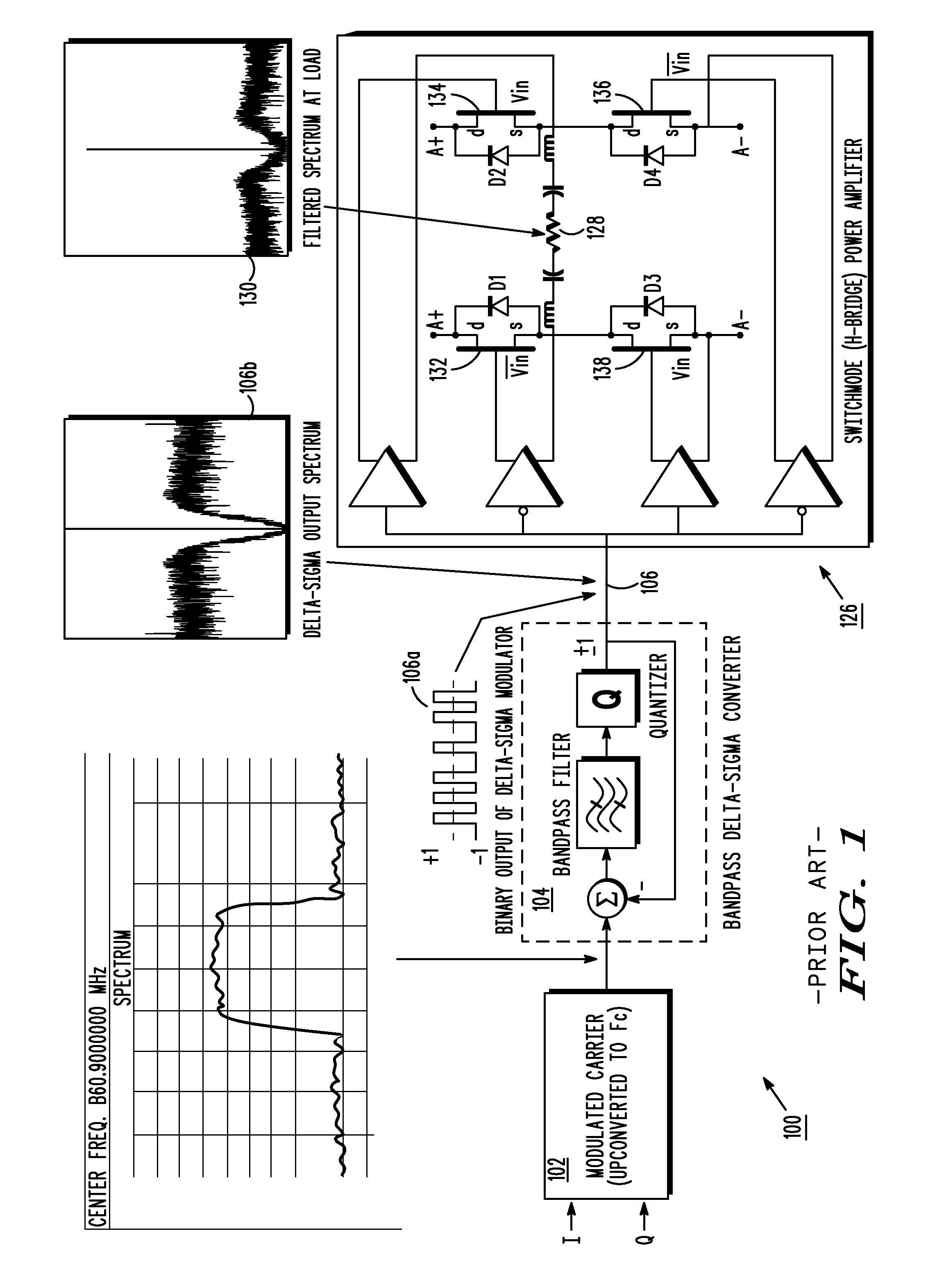
As many modulation systems such as CDMA and OFDM statistically spend much time at low power levels, the constant drive of the binary waveform implies the stage gain of the power amplifier will be low.
In turn, the low gain requires significant drive power to be applied to the PA, resulting in low efficiency operation of the overall system.

Method used


Image

  • Method and apparatus for direct digital to radio frequency conversion
  • Method and apparatus for direct digital to radio frequency conversion
  • Method and apparatus for direct digital to radio frequency conversion

Examples


Embodiment Construction

[0023]Before describing in detail various embodiments in accordance with the present invention, it should be observed that the embodiments reside primarily in combinations of method steps and apparatus components related to Direct Digital to Radio Frequency (“DDRF”) conversion and transmission. Accordingly, the apparatus components and method steps have been represented where appropriate by conventional symbols in the drawings, showing only those specific details that are pertinent to understanding the embodiments of the present invention so as not to obscure the disclosure with details that will be readily apparent to those of ordinary skill in the art having the benefit of the description herein.

[0024]In this document, relational terms such as first and second, top and bottom, and the like may be used solely to distinguish one entity or action from another entity or action without necessarily requiring or implying any actual such relationship or order between such entities or acti...


PUM


Abstract

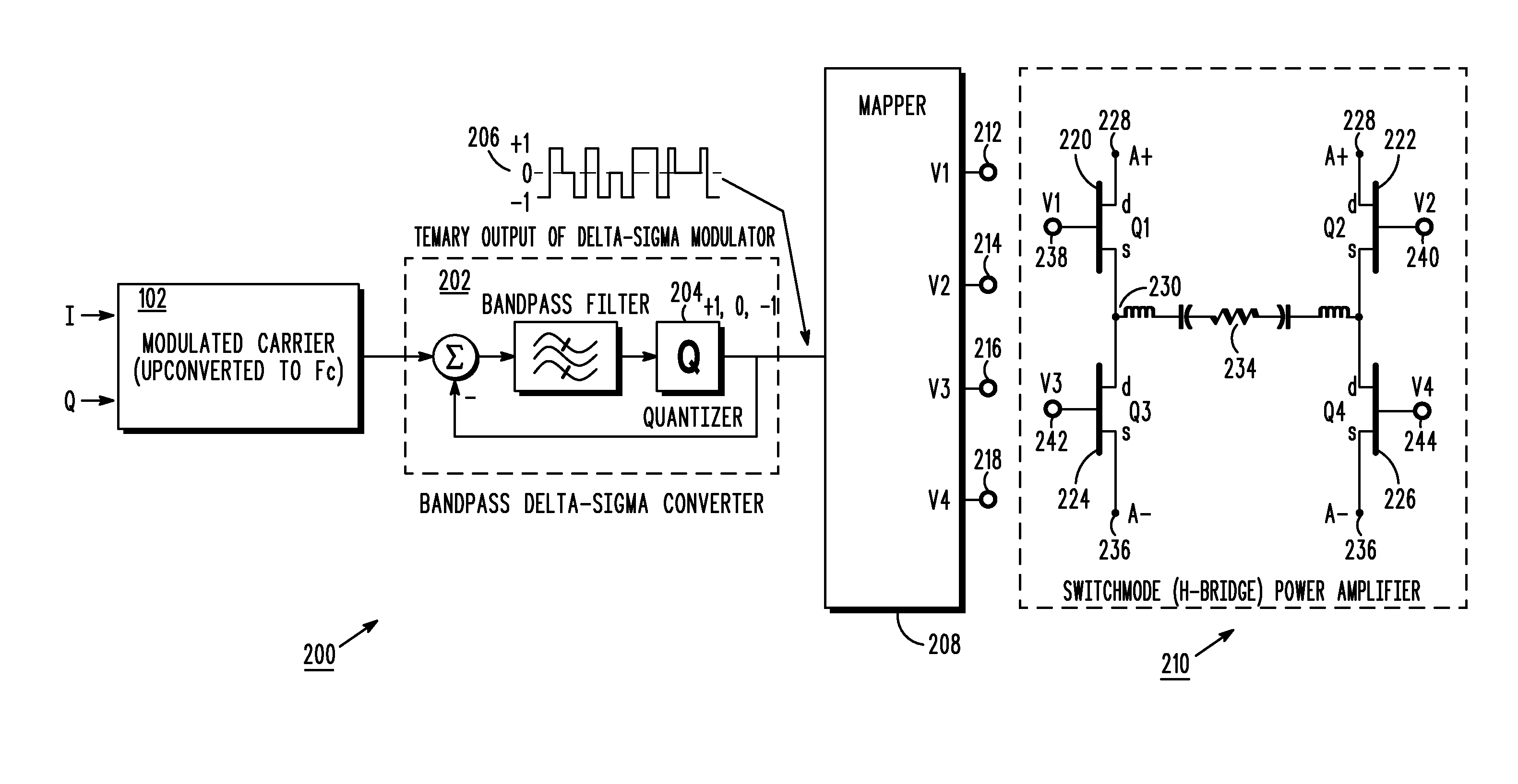
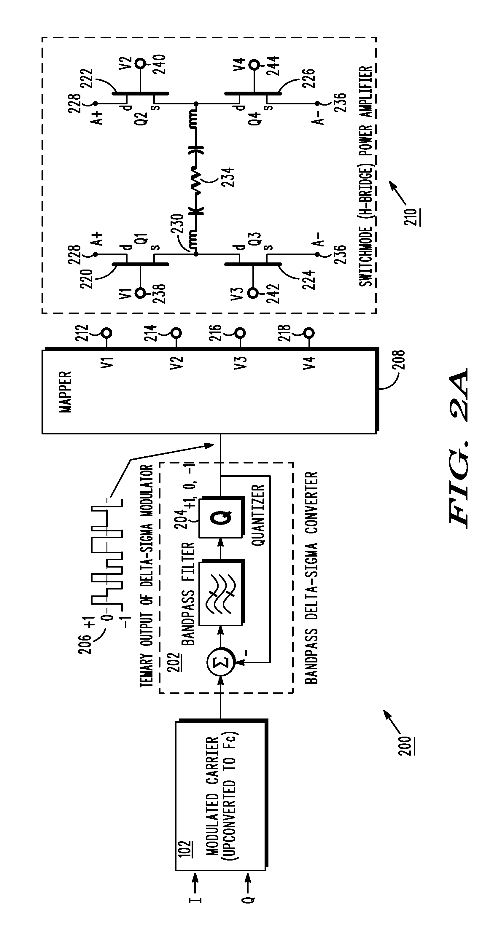
A method and apparatus for direct conversion of digital data to high power RF signals, known as DDRF. The method and apparatus receive a digital signal, create a digital modulated signal therefrom, and amplify the modulated signal with an H-bridge Power Amplifier for transmission. DDRF uses a multi-level H-bridge amplification circuit to establish a more power efficient digital transmitter.

Description

FIELD OF THE INVENTION[0001]The present invention relates generally to telecommunication and power amplification. The invention relates, more particularly, to conversion of digital data to high power RF signals and to power amplification systems suitable for use in high efficiency RF equipment.BACKGROUND[0002]The development of highly efficient radio transmitters has been an objective of engineers since the 1930's. Recent developments in digital signal processing hardware have made possible the generation of multi-gigabit-per-second serial data streams. Such high speed data streams have been investigated for use as the driving waveform in high efficiency transmitters, in particular those employing switch mode Radio Frequency (RF) power amplifiers. An extension of this concept is the development of a transmitter which efficiently converts digital information directly to a radio frequency signal. Thus, there has been a push not only for highly efficient transmitters, but also for the ...

Claims


Application Information

Patent Timeline
IPC IPC(8): H03F3/38
CPCH03F3/195H03F3/2173H03F3/245H03F2200/331H03F2200/336H03F2200/451
Inventor CYGAN, LAWRENCE F.WILLIAMS, CURTIS M.KHAN, ANDREW M.
Owner GOOGLE TECH HLDG LLC
Learn More