
Correlated magnetic light and method for using the correlated magnetic light

a technology of correlated magnetic light and correlated magnetic light, which is applied in the field of light, can solve the problems of inoperable light, preventing the creation of proper watertight seals, harsh environments for underwater lights,

Inactive Publication Date: 2010-11-02
CORRELATED MAGNETICS RES LLC
View PDF50 Cites 34 Cited by
  • Summary
  • Abstract
  • Description
  • Claims
  • Application Information

AI Technical Summary

Benefits of technology

"The present invention provides an underwater light with a releasable sealed and secured portion. The light includes a first field emission structure and a second field emission structure that interact with each other. Each field emission source has a position and polarity that corresponds to a desired spatial force function. The light can be released from the second portion when the first and second field emission structures are misaligned. The invention also provides a method for accessing the light for maintenance or replacement of a part. The technical effects of the invention include improved sealing and securement of the light, as well as more efficient and precise alignment of the field emission structures for optimal performance."

Problems solved by technology

During use, underwater lights are subjected to harsh environments that include extreme pressures, temperatures and other types of physical abuse.
One problem with threaded ends occurs if the cap is not screwed on tight enough.
This can prevent the creation of the proper watertight seal.
Additionally, users can easily cross-thread the cap also resulting in an improper seal and thereby permitting leaking to occur which often renders the light inoperable.
The threads have also been shown to loosen when exposed to different temperatures and physical abuse during underwater use.
The spring's compression factor has been shown to create problems.
First, if the spring's compression factor is too much it can create difficulties in properly sealing and securing the end of the light resulting in a poor seal or cross-threaded connection.
Second, utilizing threaded connections to secure an end or access lid of the light, over time, can reduce the spring's compression, which can result in the loss of the necessary electrical connection between the battery and the light bulb.

Method used


Image

  • Correlated magnetic light and method for using the correlated magnetic light
  • Correlated magnetic light and method for using the correlated magnetic light
  • Correlated magnetic light and method for using the correlated magnetic light

Examples


Embodiment Construction

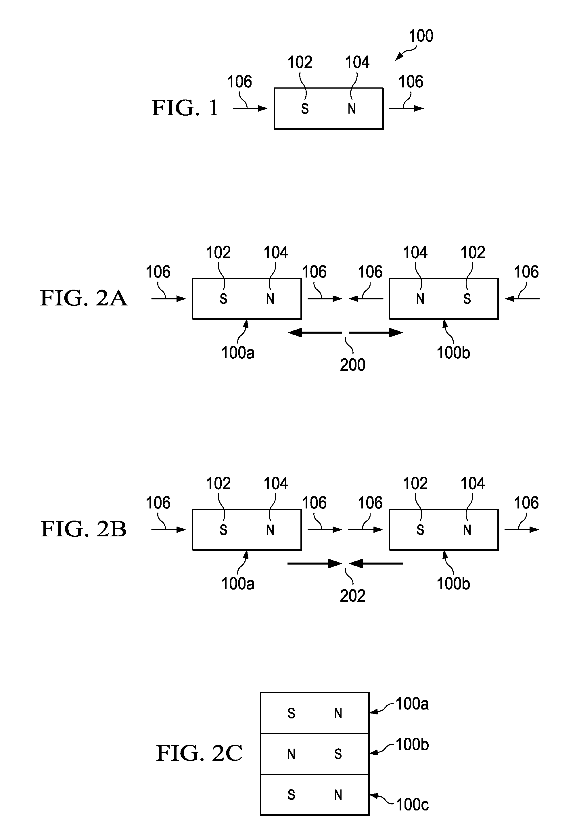
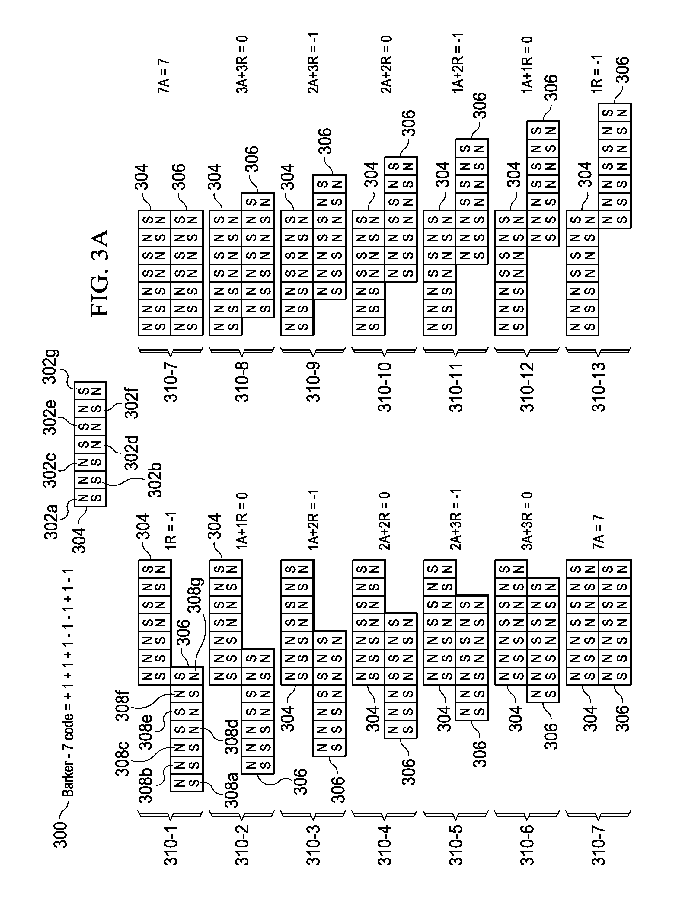
[0019]The present invention includes a light which utilizes correlated magnetic technology in place of traditional mechanical fasteners to releasably secure and seal an end or an access lid to allow a user to access at least a portion of the interior of the light to perform maintenance such as but not limited to replacing a light bulb or changing a power source. It is further contemplated within the scope of the present invention that the light also utilizes correlated magnetic technology to be releasably secured to a variety of objects such as but not limited to a scuba dive harness, scuba belt, a storage wall, or rack. The light utilizes correlated magnetic technology and is a significant improvement over a conventional light which employ threads, clamps, rings or other known fastening devices to enable the connection and sealing of an end or lid to the body of the light or enables a light to be releasably secured to an object (e.g., scuba dive harness, storage rack). This signifi...


PUM

PropertyMeasurementUnit
magnetic fieldaaaaaaaaaa
spatial forceaaaaaaaaaa
forceaaaaaaaaaa

Abstract

A light and method are described herein that use correlated magnets to enable at least one end to be secured and removed from the body of the light. Some examples of such a light include a scuba light, an underwater light, a flashlight, a submersible pool light, an emergency light, a floating light, an aquarium light or a vehicle light. Furthermore the force created by the correlated magnets mounted on the at least one end and the body creates a seal there between to substantially isolate the interior portion of the light from materials and / or matter in its external environment. Additional correlated magnets mounted in the body of the light enable the light to be secured to numerous second objects such as but not limited to scuba harnesses, belts, gloves or storage racks.

Description

CROSS REFERENCE TO RELATED APPLICATION[0001]This application is a continuation-in-part application of U.S. patent application Ser. No. 12 / 476,952 filed on Jun. 2, 2009 and entitled “A Field Emission System and Method”, which is a continuation-in-part application of U.S. patent application Ser. No. 12 / 322,561 filed on Feb. 4, 2009 and entitled “A System and Method for Producing an Electric Pulse”, which is a continuation-in-part application of U.S. patent application Ser. No. 12 / 358,423 filed on Jan. 23, 2009 and entitled “A Field Emission System and Method”, which is a continuation-in-part of U.S. patent application Ser. No. 12 / 123,718 filed on May 20, 2008 and entitled “A Field Emission System and Method”. The contents of these four documents are hereby incorporated herein by reference.TECHNICAL FIELD[0002]The present invention is related to a light that uses correlated magnets that enable a person to easily secure and remove a sealed portion of the light permitting access to the i...

Claims


Application Information

Patent Timeline
Patent Type & Authority Patents(United States)
IPC IPC(8): F21V21/00H01F7/02
CPCG01D18/00H01F7/0215H01F7/0263
Inventor FULLERTON, LARRY W.ROBERTS, MARK D.
Owner CORRELATED MAGNETICS RES LLC
Learn More