
Detector system for detecting the direction in which an item passes through a determined boundary zone

a detection system and boundary zone technology, applied in the field of transportation logistics and of parcels, packets or pallet handling, can solve the problems of determining whether a parcel is inside or outside a precise space, such as the threshold of a vehicle, which has not yet been addressed

Active Publication Date: 2010-10-26
NEOPOST TECH SA
View PDF23 Cites 11 Cited by
  • Summary
  • Abstract
  • Description
  • Claims
  • Application Information

AI Technical Summary

Benefits of technology

"The present invention proposes a detector system for detecting an item passing through a boundary zone to ensure that it is on one side or the other of the boundary. The detector system includes two read-interrogate elements and processor means connected to the read-interrogate elements. The processor means determines the direction in which the item passes through based on the order in which the two regions are crossed. The detector system can also include wireless or wired communications means for transmitting the identification data and data relating to the travel direction of the item to external management means. Additionally, the detector system may include sound and / or light indicator means. The technical effect of the invention is to solve the problem of misdirected items and ensure safe and efficient loading and unloading of goods."

Problems solved by technology

However, the essential problem of determining whether a parcel is inside or outside a precise space, such as a vehicle, whose threshold it has crossed, has not yet been addressed.
That problem arises frequently in the field of transport logistics in which numerous parcels are mislaid or stolen.

Method used


Image

  • Detector system for detecting the direction in which an item passes through a determined boundary zone
  • Detector system for detecting the direction in which an item passes through a determined boundary zone
  • Detector system for detecting the direction in which an item passes through a determined boundary zone

Examples


Embodiment Construction

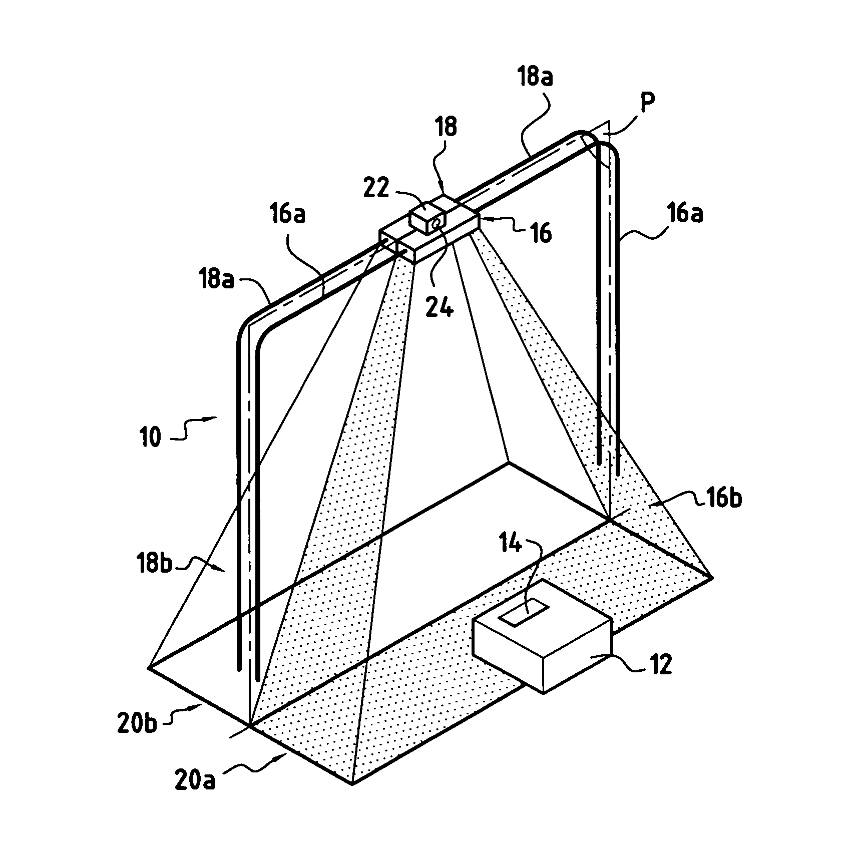
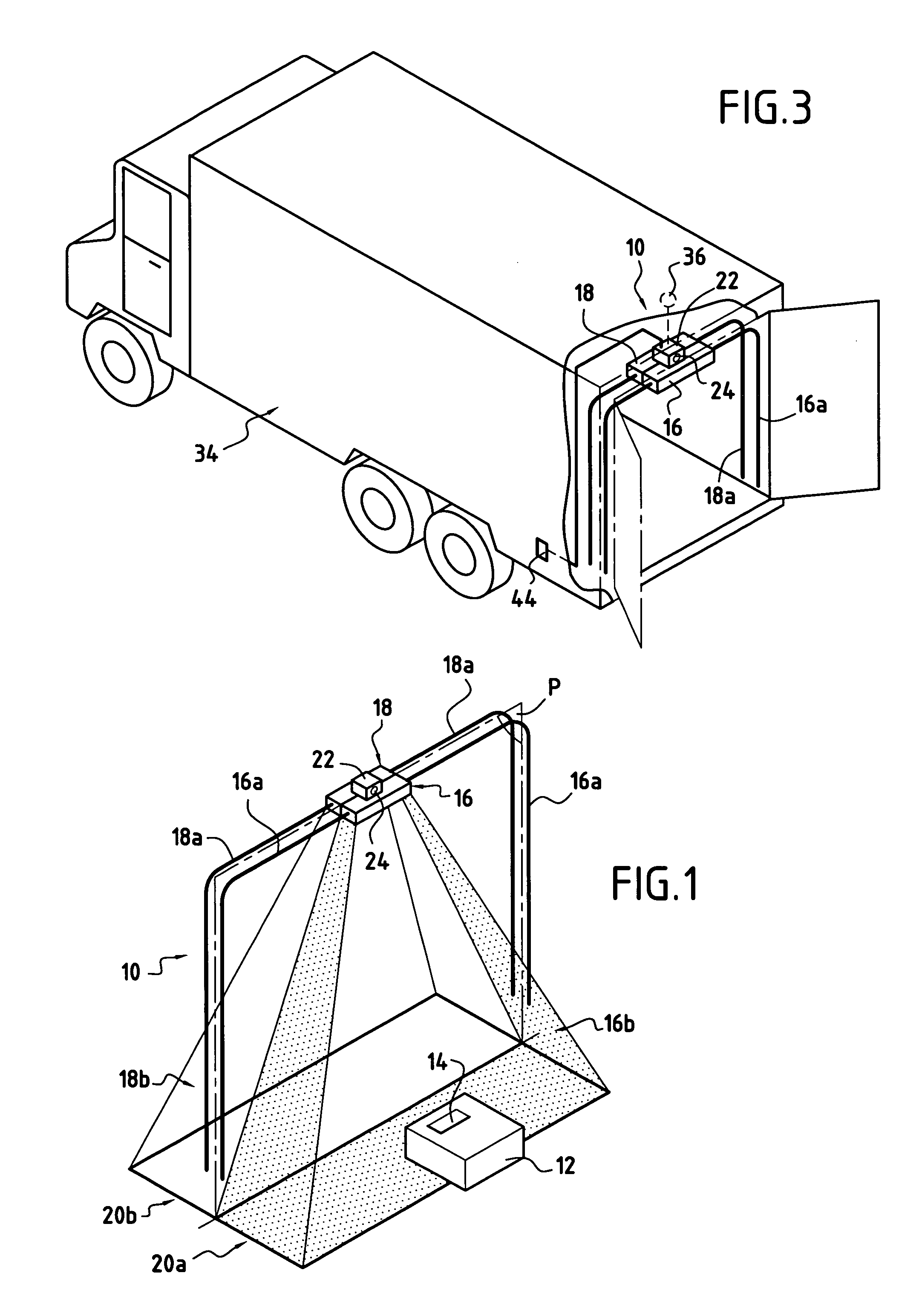
[0020]In accordance with the invention, FIG. 1 shows a detector system 10 for detecting the direction in which an item 12 passes through a boundary crossing zone between two distinct spaces. By way of example, the item 12 is a parcel or a packet, and it includes electronic identification means or an RFID tag 14.

[0021]The detector system 10 includes a first read-interrogate element 16 having a first antenna 16a, and a second read-interrogate element 18 having a second antenna 18a. Each of the two antennas 16a, 18a can be in the form of a loop.

[0022]The two read-interrogate elements 16, 18 can be adjoining or separate as a function of the configuration of the boundary crossing zone. The first antenna 16a of the first read-interrogate element 16 defines a first detection lobe 16b, and the second antenna 18a of the second read-interrogate element 18 defines a second detection lobe 18b that does not overlap the first detection lobe 16b. At their closest, the two detection lobes 16b, 18b ...


PUM


Abstract

The invention relates to a goods transport vehicle including a detector system for detecting the direction in which an item passes through a loading / unloading door on the vehicle, the detector system including:a first read-interrogate element including a first antenna having a first detection lobe, the first read-interrogate element monitoring a first region situated on one side of the loading / unloading door;a second read-interrogate element including a second antenna having a second detection lobe that does not overlap the first detection lobe, the second read-interrogate element monitoring a second region situated on the other side of the loading / unloading door; andprocessor means connected to the first and second read-interrogate elements, the processor means determining the direction in which the item passes through as a function of the order in which the two regions are crossed.

Description

CROSS-REFERENCE TO RELATED APPLICATIONS[0001]This applications claims priority from French Patent Application No. 04 00937 filed Jan. 30, 2004.FIELD OF THE INVENTION[0002]The present invention relates to the field of transport logistics and of parcel, packet, or pallet handling.PRIOR ART[0003]The use of Radio Frequency Identification Device (RFID) technology is well known in logistics for tracking and identifying parcels and for processing information relating to all of the operations and services involved in the entire transport chain.[0004]However, the essential problem of determining whether a parcel is inside or outside a precise space, such as a vehicle, whose threshold it has crossed, has not yet been addressed.[0005]That problem arises frequently in the field of transport logistics in which numerous parcels are mislaid or stolen.OBJECT AND SUMMARY OF THE INVENTION[0006]An object of the present invention is thus to solve the above-mentioned problem by proposing a detector syst...

Claims


Application Information

Patent Timeline
Patent Type & Authority Patents(United States)
IPC IPC(8): G08B21/00G01V3/10G07C9/00G08B13/14G08B13/24
CPCG01V3/104G08B13/14G08B13/2454
Inventor VENTURE, GUYLIEVRE, JEROME
Owner NEOPOST TECH SA
Learn More