
Hybrid power supply and power management method thereof

a hybrid power supply and power management technology, applied in emergency power supply arrangements, electrochemical generators, emergency supply, etc., can solve the problems of low conversion efficiency of fuel cell batteries, damage to rechargeable batteries b, and new problems

Active Publication Date: 2010-10-26
IND TECH RES INST
View PDF12 Cites 122 Cited by
  • Summary
  • Abstract
  • Description
  • Claims
  • Application Information

AI Technical Summary

Benefits of technology

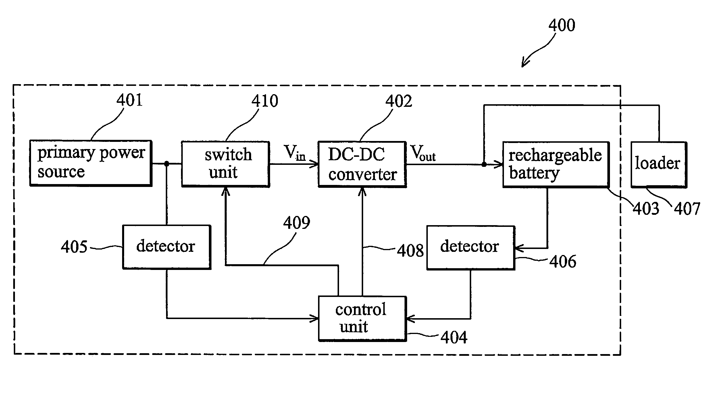
The invention provides a power management method and system for a hybrid power supply using a primary power source and a rechargeable battery as control factors. The method involves acquiring the power stored in the rechargeable battery and controlling the primary power source to output a first value of a first electrical parameter when the energy level of the rechargeable battery does not exceed a predetermined value. The system includes a primary power source, a rechargeable battery, a control unit, and a DC-DC converter, which performs a power management procedure based on the energy level of the rechargeable battery and the first electrical parameter to adjust the output voltage of the DC-DC converter. The technical effect of the invention is to optimize the use of power from the primary and rechargeable batteries in a hybrid power supply system, leading to improved efficiency and reliability.

Problems solved by technology

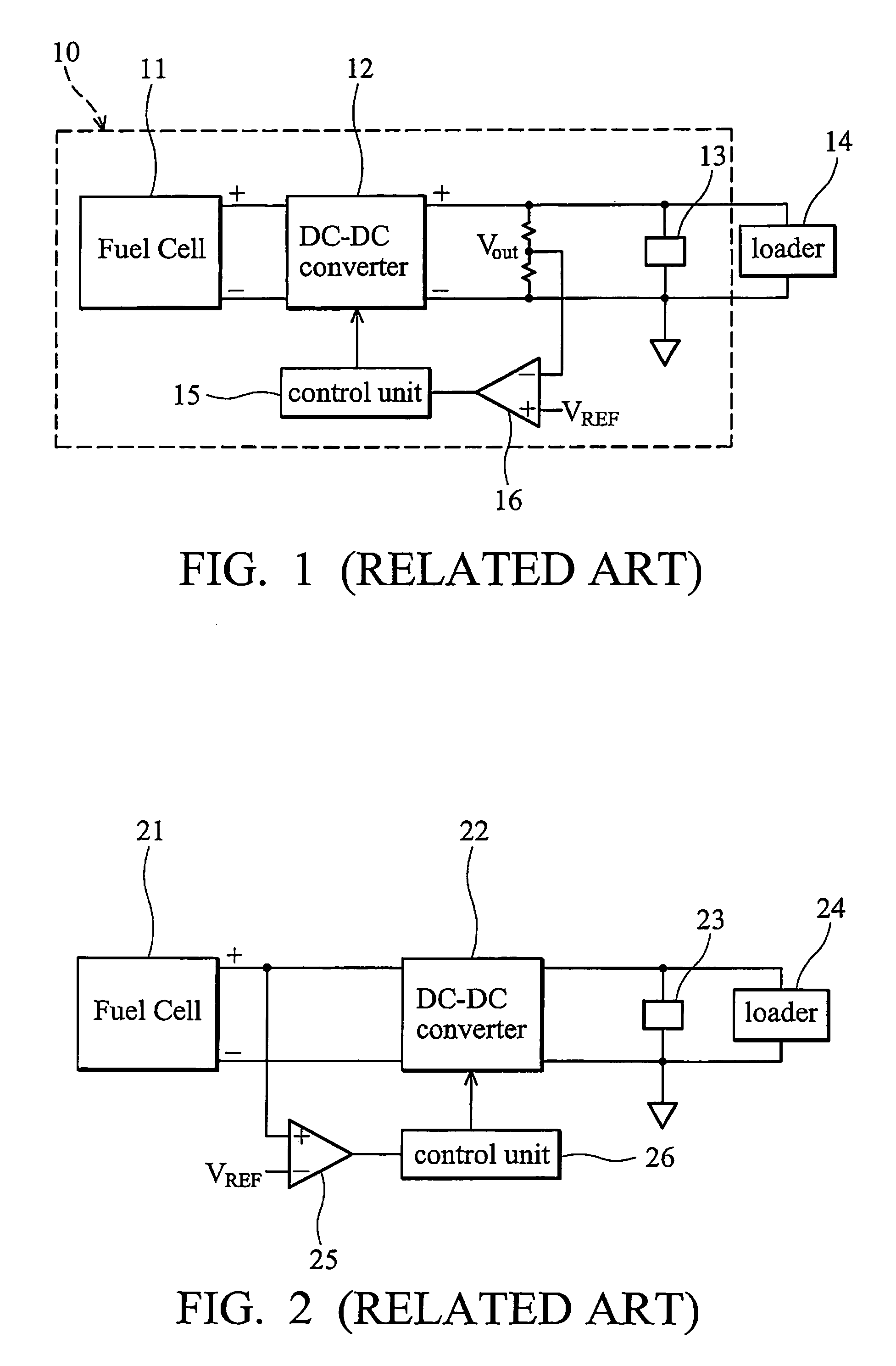
When the fuel cell battery outputs at maximum power, however, the low conversion efficiency of the fuel cell battery decreases the numbers of hour fuel cell battery can be used.
When the rechargeable battery 23 is at full charge or the voltage of the rechargeable battery 23 is equal to a cutoff voltage, however, the rechargeable battery 23 can no longer adjust the fuel cell battery 21 and may damage the rechargeable battery 23.
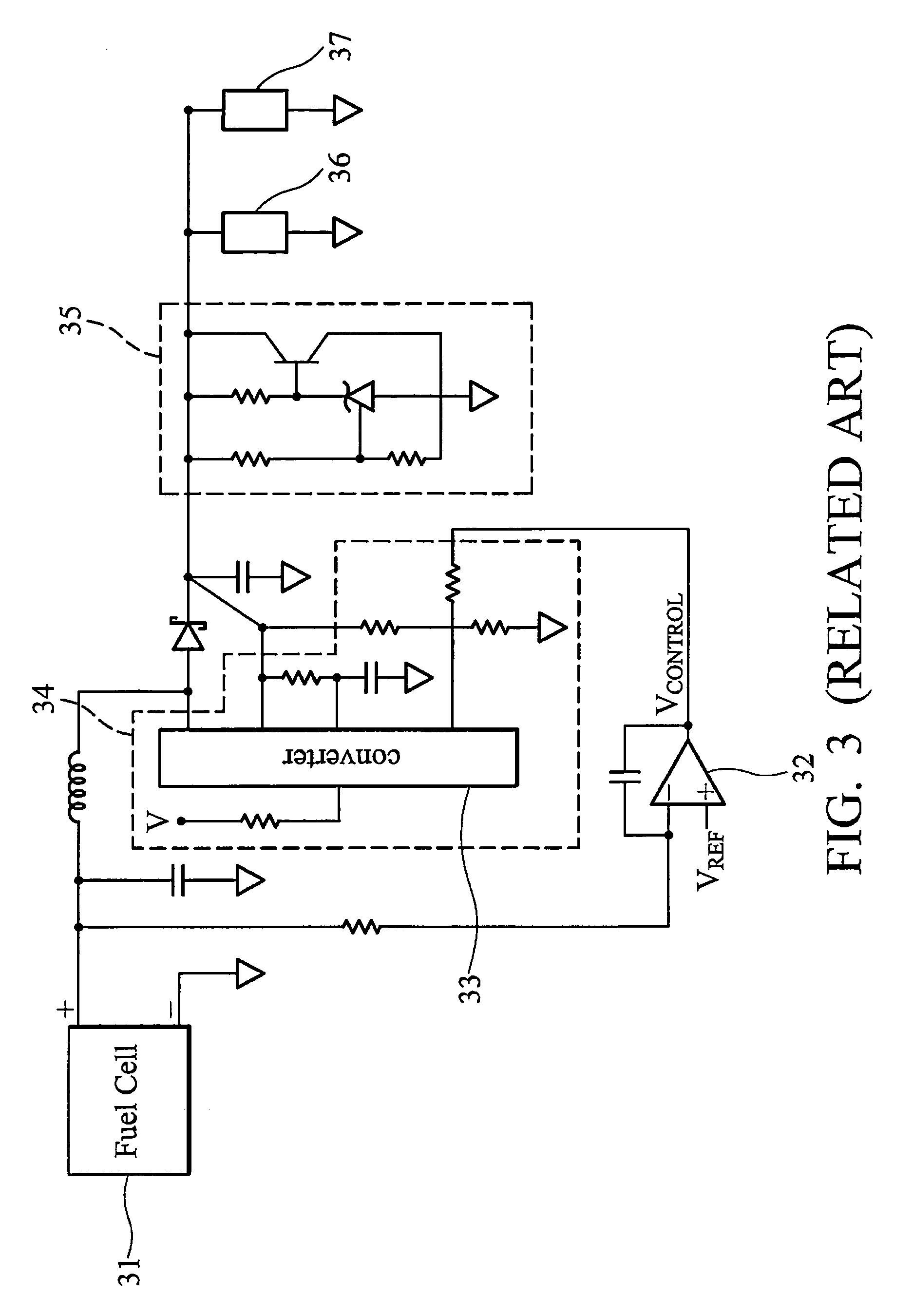
Although, the problem of the rechargeable battery 36 is solved, the wasted energy of the fuel cell battery 31 and heat generated by the protection circuit causes new issues.
Furthermore, when the power stored in the rechargeable battery 36 is exhausted, the hybrid power supply fails.

Method used


Image

  • Hybrid power supply and power management method thereof
  • Hybrid power supply and power management method thereof
  • Hybrid power supply and power management method thereof

Examples


third embodiment

[0047]FIG. 9 is a schematic diagram of the of the hybrid power system of the invention. In this embodiment, the circuit of the control unit 96 is merely provided as an example for the purpose of illustration, and is not intended to limit the control unit 96. The current measurement unit 94 detects and transforms the current IF of the fuel cell battery 91 into a voltage signal Vin, and the voltage measurement unit 95 detects and transforms the voltage VS of the rechargeable battery 93 into a voltage signal Vout. In this embodiment, the current detector 94 can be formed of a Hall element capable of directly detecting the current of fuel cell battery 91, or by measuring a voltage drop of a resistor which the output current IF of fuel cell battery 91 passes by, and then transmitting the voltage signal Vin to the control unit 96.

[0048]In this embodiment, the maximum current of the fuel cell battery 91 is 1.2 A and the corresponding voltage is 2.5V. The operation of the control unit 96 is...

fourth embodiment

[0050]FIG. 11 is a schematic diagram of the hybrid power system of the invention. The power measurement unit 11 measures and transforms the power of fuel cell battery 111 into a voltage signal and the voltage measurement 116 measures and transforms the voltage of the rechargeable battery 113 into a voltage signal. The control unit 114 receives the voltage signal from the power measurement unit 11 and the voltage measurement 116 to generate a control signal 118. In this embodiment, the maximum output power of the fuel cell battery 111 is 10 W and the corresponding voltage is 2.5V. When the voltage of the rechargeable battery 113 does not exceed 12.25V, the fuel cell battery 111 outputs the maximum power to the DC-DC converter 112 according to the control signal from the control unit 114. In this embodiment, a multiple point control method also can be applied to the voltage of the fuel cell battery 111. When the voltage of the rechargeable battery 113 is between 11.4V and 12.25V, the ...

fifth embodiment

[0051]FIG. 12 is a schematic diagram of the hybrid power system of the invention. In this embodiment, a maximum power point tracking (MPPT) unit 125 is applied to track the maximum power point of the fuel cell battery 121. The control unit 124 generates a control signal to control the DC-DC converter 122 according to a first voltage signal from the MPPT unit 125 and a second voltage signal from the voltage measurement unit 126. When the rechargeable battery 123 is at full charge, the output voltage of the DC-DC converter 122 is fixed according to the control signal 128 from the control unit 124 and the output power of the fuel cell battery 121 is determined by the loader 127. When the voltage of the rechargeable battery 123 does not exceed a predetermined value, the fuel cell battery 121 outputs the maximum power to the DC-DC converter 122 for rapid of charge the rechargeable battery 123.


PUM

PropertyMeasurementUnit
voltageaaaaaaaaaa
voltageaaaaaaaaaa
voltageaaaaaaaaaa

Abstract

The invention provides a power management method for a hybrid power supply, comprising providing a primary power source, providing a rechargeable battery, providing a DC-DC converter, acquiring an amount of the power stored in the rechargeable battery, and when the energy level of the rechargeable battery does not exceed a first predetermined value, the DC-DC converter controls the primary power source to output a first value of a first electrical parameter.

Description

BACKGROUND OF THE INVENTION[0001]1. Field of the Invention[0002]The present invention relates to a power supply and a power management method thereof, and more particularly to a hybrid power supply and a power management method thereof.[0003]2. Description of the Related Art[0004]Fuel cell batteries have been identified as a clean, highly efficient means of energy storage and a means for converting energy to useable electricity. Methanol fuel cells in particular have been identified not only as a means of storing energy and converting stored energy to electricity but also as part of a renewable (as opposed to exhaustible) energy system based on methanol. When the fuel cell battery outputs at maximum power, however, the low conversion efficiency of the fuel cell battery decreases the numbers of hour fuel cell battery can be used. Thus, a hybrid power supply comprising a fuel cell battery is desirable.[0005]FIG. 1 is a schematic diagram of a conventional hybrid power supply 10. In FIG...

Claims


Application Information

Patent Timeline
Patent Type & Authority Patents(United States)
IPC IPC(8): H01M10/46
CPCH02J9/061Y02B90/14Y02B10/72H02J2001/004H02J2300/30Y02B10/70Y02B90/10B60Y2304/05B60Y2304/07
Inventor CHOU, YUH-FWULAI, CHIOU-CHUSHEN, SHENG-YONG
Owner IND TECH RES INST
Learn More