
Dispenser pump

a technology of pump and pump body, which is applied in the direction of piston pump, positive displacement liquid engine, instruments, etc., can solve the problems of superproportional increase of overall axial height and aggressive liquid attack on metallic reset, and achieve compact and durable structure

Active Publication Date: 2010-10-26
APTAR DORTMUND GMBH
View PDF21 Cites 4 Cited by
  • Summary
  • Abstract
  • Description
  • Claims
  • Application Information

AI Technical Summary

Benefits of technology

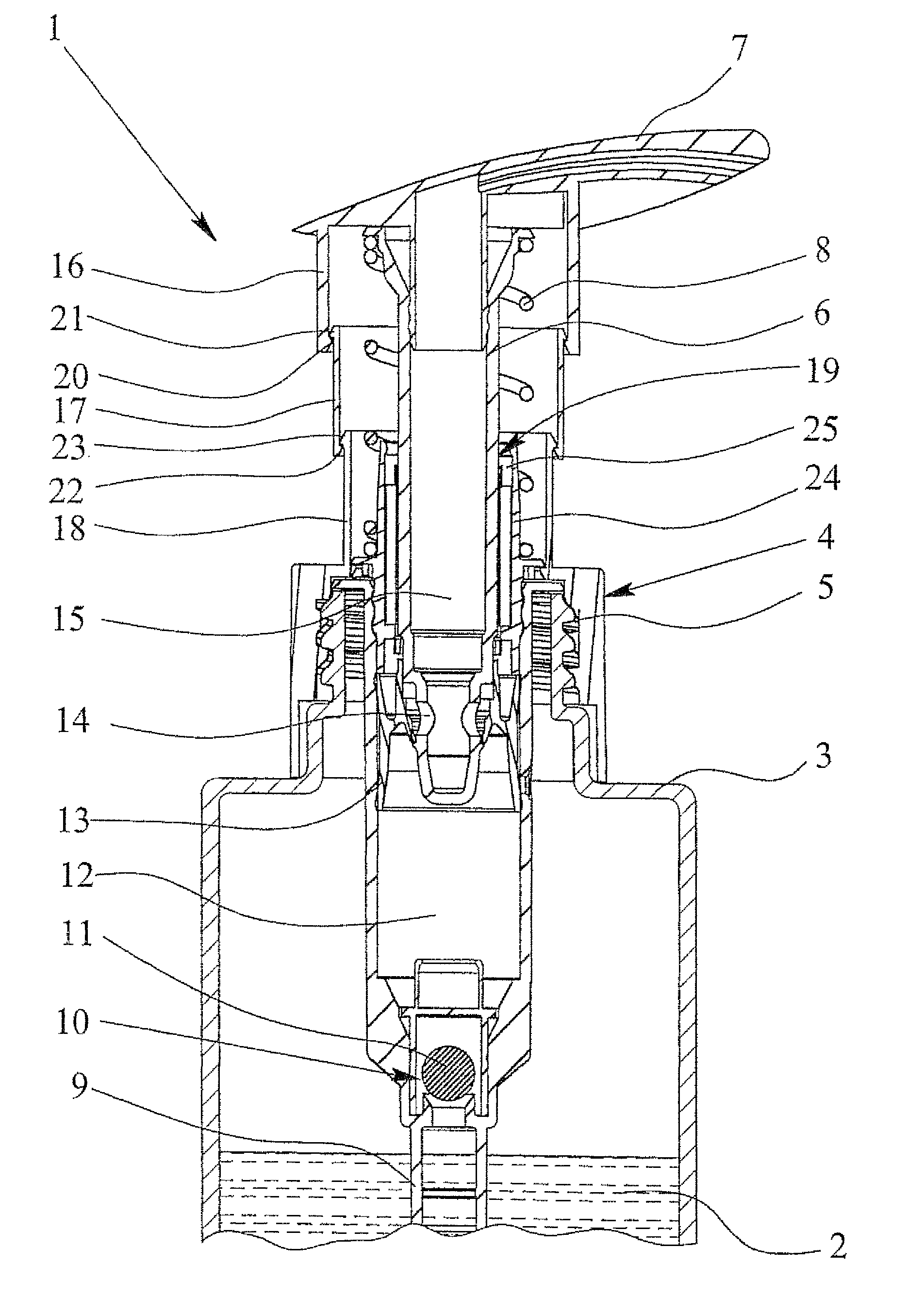
[0008]The object of this invention is to devise a dispenser pump which is suited for viscous, aggressive liquids, and especially, in which a compact and durable structure with splash protection can be implemented.
[0010]The first aspect of this invention is that the dispenser pump has at least one additional sleeve section which is connected to the second sleeve section extending toward the pump housing and which can be pushed into the second sleeve so that three or more sleeve sections form a telescopically extendable splash protection around the pump shaft between the pump housing and the dispenser head. Thus, when the pump stroke is increased, the additional overall axial height which is necessary beyond the increase of the pump stroke is greatly reduced compared to the prior art and accordingly enables a compact structure of the dispenser pump. Furthermore a simple and thus economical structure with effective splash protection results.
[0011]A second aspect of this invention which can also be implemented independently consists in placing a spring which is intended for resetting the pump shaft radially outside of the pump shaft and / or between the pump housing and the dispenser head, therefore outside of the areas which come into contact with the liquid to be pumped. In this way it is possible to prevent the spring which conventionally is made of metal from being attacked by increasingly aggressive liquids.
[0012]Preferably, the check valve, especially its valve ball, is likewise made of plastic. In this way, it is possible to prevent aggressive liquids from attacking the dispenser pump and / or metal ions from being taken up by the liquids and thus contaminating them.

Problems solved by technology

Reducing the size of the pump stroke with the result of increasing the diameter of the pump cylinder, on the other hand, would have extreme disadvantages or problems in order to be able to intake liquids or other products of higher viscosity and to deliver them with an acceptable expenditure of force.
In the known dispenser pumps, splash protection leads to a superproportional increase of the overall axial height when the pump stroke is increased.
Furthermore, it is disadvantageous in the known dispenser pump that very aggressive liquids can attack the metallic reset spring or a metallic check valve.

Method used


Image

  • Dispenser pump
  • Dispenser pump

Examples


Embodiment Construction

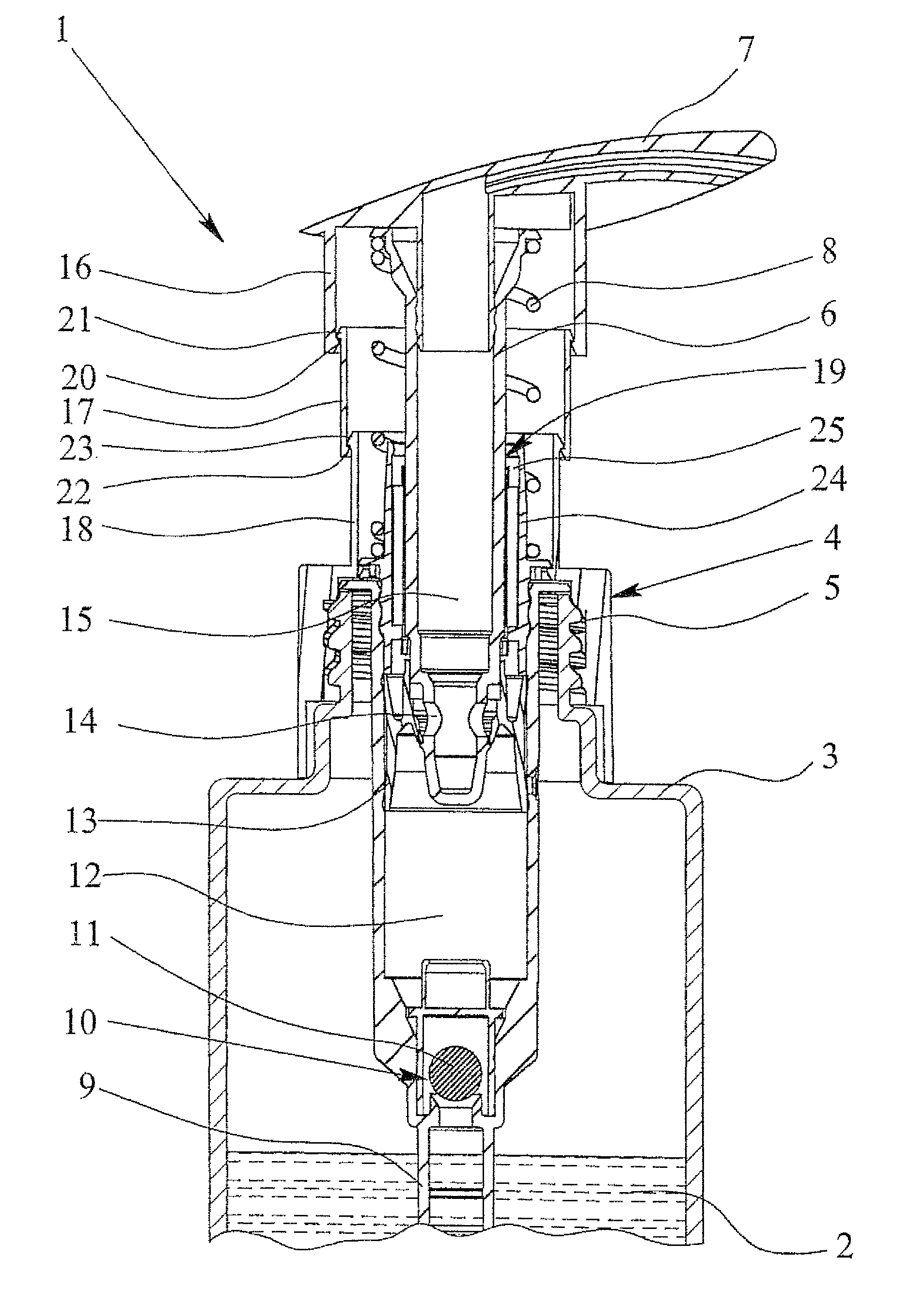
[0016]The illustrated dispenser pump 1 is used to deliver a liquid 2, such as a washing lotion for cleaning the human body, a body care product, a cleaning product or the like. The liquid 2 can be especially relatively viscous and / or aggressive.

[0017]The container 3 is assigned to the dispenser pump 1; the dispenser pump 1, if necessary, is detachably mounted on it. Thus, for example, replacement of the container 3 and / or replenishment of the liquid 2 can take place.

[0018]The dispenser pump 1 has a pump housing 4 which can be attached to the container 3, in the illustrated embodiment, by means of a collar section or threaded section 5 which is preferably directly molded on.

[0019]The dispenser pump 1, furthermore, has a pump shaft 6 and a dispenser head 7 which is located on its free end.

[0020]The pump shaft 6 can, be pressed in manually against the force of a spring 8 which causes resetting. The spring 8 pretensions the pump shaft 6 with the dispensing head 7 up into the initial pos...


PUM


Abstract

A dispenser pump (1) that has a manually insertable pump shaft (6) which is surrounded by at least three sleeve sections (16, 17, 18) that can be slid into each other in a telescopic manner. A return spring (8) is preferably disposed between pump shaft (6) and the sleeve sections (16, 17, 18). All parts of the dispenser pump (1), which enter in contact with a liquid that is to be pumped, are made of plastic.

Description

BACKGROUND OF THE INVENTION[0001]1. Field of the Invention[0002]This invention relates to a dispenser pump for dispensing a liquid from a container of the type having a pump housing which can be attached to the container, a pump shaft which can be moved relative to the pump housing, especially can be manually pressed into it, a dispenser head on the pump shaft.[0003]The term “dispenser pump” is defined especially as a metering pump or manually activated pump for delivery of liquids, such as washing lotions for cleaning the human body, body care products, cleaning products, cosmetics, but also lubricants or the like.[0004]2. Description of the Related Art[0005]European Patent Application EP 0 806 249 B1, upon which this invention is based, discloses a dispenser pump for delivery of liquid from a container. The pump housing can be attached to the container and holds a pump shaft which can be manually pressed into the pump housing against spring force by the user pressing on the dispen...

Claims


Application Information

Patent Timeline
Patent Type & Authority Patents(United States)
IPC IPC(8): G01F11/00B05B11/00F04B9/14
CPCB05B11/3001B05B11/3074B05B11/1001B05B11/1074
Inventor SCHULTE, FRANK ERWINBOHNISCH, KARSTENNEUHAUS, REINHARD HEINRICHKNOBLICH, CRISTINMENZEL, NORBERT
Owner APTAR DORTMUND GMBH
Learn More