
Method and device for activating an electric parking brake

a technology of electric parking brake and electric motor, which is applied in the direction of automatic initiation, braking system, transportation and packaging, etc., can solve the problems of increased labor and expense, no longer fully controllable vehicles, and increased construction and production costs

Active Publication Date: 2010-10-19
VOLKSWAGEN AG
View PDF12 Cites 19 Cited by
  • Summary
  • Abstract
  • Description
  • Claims
  • Application Information

AI Technical Summary

Benefits of technology

The present invention provides a method and device for activating an electric parking brake of a motor vehicle to reliably stop it during parking. The device detects the initiation of a shut-down operation and activates the electric parking brake only afterward, allowing the vehicle to be parked securely even when the energy store of the vehicle is low. The activation of the electric parking brake may be dependent on the operating state of the energy supply, the angle of inclination of the vehicle, and / or the standstill of the vehicle. The device includes an activation device and a detection device for detecting the initiation of the shut-down operation. The method may involve maintaining the operation of the drive motor for a period of time and generating a signal to shut down the drive motor only when the shut-down operation is detected or the vehicle is at a standstill.

Problems solved by technology

Dangerous situations may occur as a result, in particular in motor vehicles in which the mechanical power of the drive motor is additionally utilized to activate a service brake of the motor vehicle.
If after shut-down of the drive motor the electrical energy in such vehicles is no longer sufficient to restart the drive motor, the vehicle is no longer fully controllable.
Disadvantageous in an auxiliary battery provided in addition to the battery of the vehicle electrical system is the effort and expense it entails with regard to construction and production.
Also, it is possible once again that the auxiliary battery will no longer have sufficient energy or is unable to store sufficient energy.

Method used


Image

  • Method and device for activating an electric parking brake
  • Method and device for activating an electric parking brake

Examples


Embodiment Construction

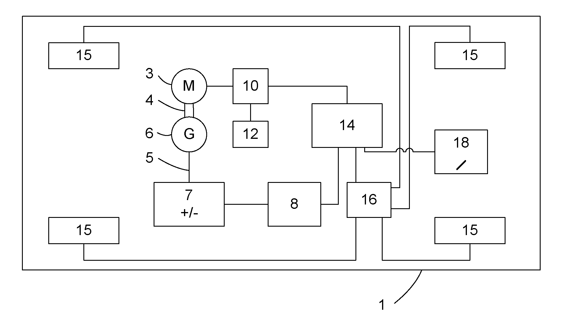
[0022]Motor vehicle 1, schematically illustrated in FIG. 1 within a rectangular frame, has a drive motor 3, which during its operation drives a generator 6 via a mechanical coupling 4. The electrical energy generated by generator 6 is fed into a vehicle electrical system 5, which has at least one energy store for storing electrical energy, e.g., a conventional vehicle battery. Vehicle electrical system 5 is connected to a battery state device 8 (such as a control device for a vehicle electrical system), which is able to determine a charge state of energy store 7, for example. A corresponding result of this determination is transmitted to a control device 14 of an electric parking brake (EPB control device in the following text), continuously and / or as required.

[0023]Drive motor 3 may be an internal combustion engine, which may be turned off and on by activating an ignition switch 12. Ignition switch 12 is connected to an engine control device 10, which is connected to drive motor 3....


PUM


Abstract

A method and a device are for activating an electric parking brake of a motor vehicle, e.g., a road motor vehicle. Initiation of a connection process is recognized for disconnecting a drive motor of the vehicle when the vehicle is parked. The electric parking brake is initially activated after the initiation of the parking step, and the drive motor is disconnected thereafter. As a result, the drive motor may be used to activate the parking brake.

Description

FIELD OF THE INVENTION[0001]The present invention relates to a method and a device for activating an electric parking brake of a motor vehicle, e.g., a road motor vehicle.BACKGROUND INFORMATION[0002]German Published Patent Application No. 198 38 886 describes an electric immobilizing brake or parking brake for a vehicle. The driver of the motor vehicle activates the electric parking brake via a push-button switch, for example. The parking brake provides that the vehicle is no longer able to move in the stopped or parked state. To achieve the immobilizing braking effect, it is possible, for example, to control the parking brake's wheel brakes arranged on the wheels of the motor vehicle by electromotor / transmission units designed to self-lock. This provides the effect of a conventional mechanical immobilization brake.[0003]Activation of the electric parking brake requires electric energy, which can be drawn from the vehicle electrical system. When turning off or parking the motor vehi...

Claims


Application Information

Patent Timeline
Patent Type & Authority Patents(United States)
IPC IPC(8): B60W10/04B60W10/18B60T7/08B60T7/10B60T7/12B60T13/74
CPCB60T7/107B60T7/12B60T13/74Y10T477/853Y10T477/814
Inventor JAGODZINSKI, VOLKER
Owner VOLKSWAGEN AG
Learn More