
Recording apparatus

a recording device and recording medium technology, applied in the field of recording devices, can solve the problems of difficult stabilization of the behavior of the recording medium, more significant disturbance, and disturbance of the recording medium

Inactive Publication Date: 2010-10-19
SEIKO EPSON CORP
View PDF13 Cites 4 Cited by
  • Summary
  • Abstract
  • Description
  • Claims
  • Application Information

AI Technical Summary

Benefits of technology

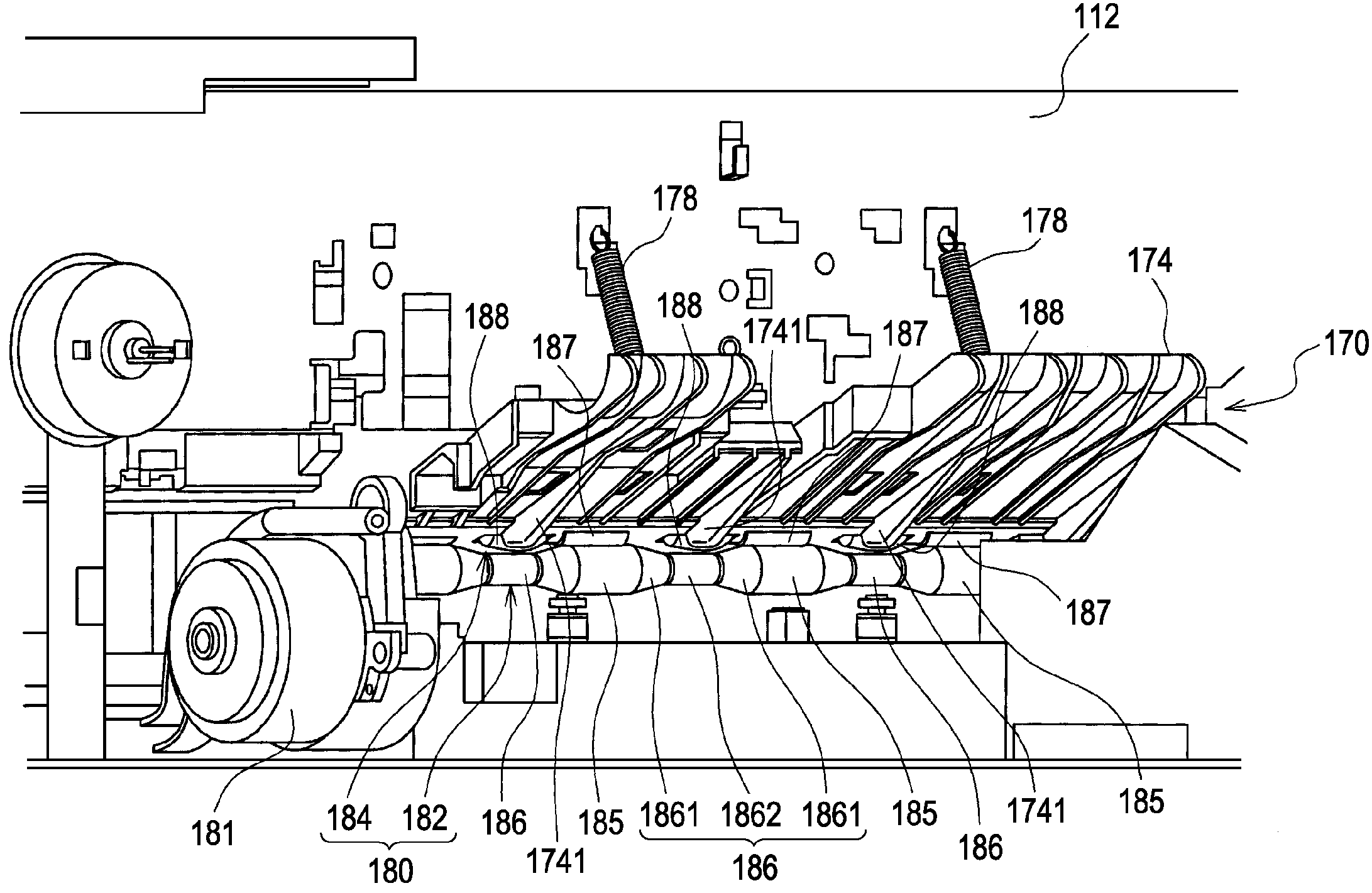
[0006]According to an aspect of the invention, a recording apparatus includes a recording head, a transport driving roller, and a transport driven roller. The recording head discharges ink onto a transported recording medium, thereby performing recording. The transport driving roller is provided on the upstream side of the recording head in the transport direction and includes driving side roller portions and depressed portions. The driving side roller portions are rotationally driven, thereby transporting the recording medium. The diameter of the depressed portions is smaller than that of the driving side roller portions. The driving side roller portions and the depressed portions are arranged in a direction perpendicular to the transport direction of the recording medium in such a manner that at least one driving side roller portion alternates with at least one depressed portion. The transport driven roller is provided opposite the transport driving roller and includes driven side roller portions and presser rollers. The driven side roller portions are driven by the driving side roller portions with the recording medium therebetween. The diameter of the presser rollers is larger than that of the driven side roller portions. The presser rollers press the recording medium toward the depressed portions. The driven side roller portions and the presser rollers are arranged in a direction perpendicular to the transport direction of the recording medium in such a manner that at least one driven side roller portion alternates with at least one presser roller. Thus, the recording medium can be corrugated with the transport driving roller and the transport driven roller and transported to the recording region of the recording head. As a result, a rapid change in the attitude of the recording medium passing between the transport driving roller and the transport driven roller can be suppressed, and so, in the recording region of the recording head, the recording medium can be transported further with the attitude stabilized.
[0007]It is preferable that the recording apparatus further include at least one bearing portion that rotatably supports at least one of the depressed portions, and the driving side roller portions be roughened, and the at least one of the depressed portion supported by the at least one bearing portion be smoother than the driving side roller portions. Thus, transporting force applied to the recording medium by the driving side roller portions and the driven side roller portions can be secured. In addition, the frictional resistance between the at least one bearing portion and the at least one of the depressed portions can be reduced, and the abrasion of the at least one bearing portion and the at least one of the depressed portions can be reduced.
[0008]It is preferable that the friction coefficient of the presser rollers be lower than the friction coefficient of the driven side roller portions. Thus, the transport impact of the presser rollers on the recording medium can be reduced.

Problems solved by technology

In the above recording apparatus, a recording medium passing through the transport roller is rapidly corrugated by the transport guide, and so the behavior of the recording medium is disturbed.
In particular, the longer the distance between the transport roller and a discharge roller is, the more significant this disturbance is.
Therefore, the wider the recording region of the recording head is in the transport direction, the more difficult it is to stabilizing the behavior of the recording medium.
Due to the disturbance of behavior of the recording medium, the recording medium and the recording head can interfere, and the accuracy of ink hitting the recording medium can be insufficient.

Method used


Image

  • Recording apparatus
  • Recording apparatus
  • Recording apparatus

Examples


Embodiment Construction

[0024]Although the present invention will be described with reference to embodiments, the following embodiments do not limit the invention according to the scope of claims. Not all combinations of characteristics described in the embodiments are necessary for solving means of the invention.

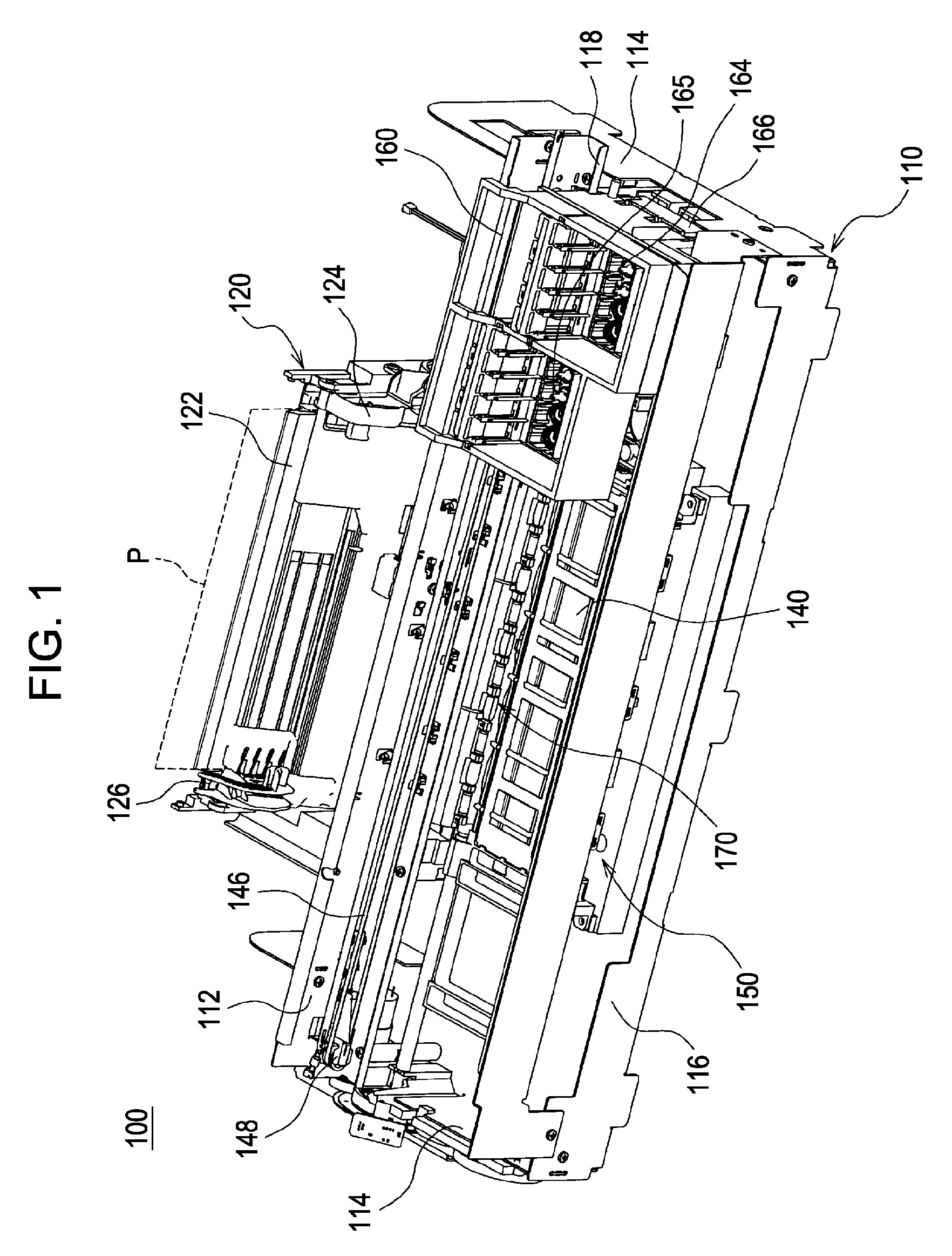
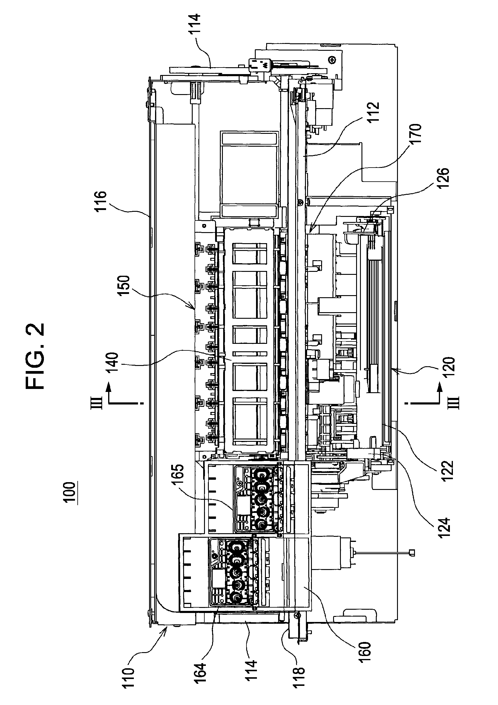
[0025]FIG. 1 is a perspective view showing the internal structure of an ink jet recording apparatus 100 according to an embodiment. FIG. 2 is a plan view showing the internal structure of the recording apparatus 100.

[0026]The upstream side in the transport direction of paper P serving as a recording medium in the recording apparatus 100, the upper side in the figure, will be referred to as the rear side in the recording apparatus 100. The downstream side in the transport direction of paper P in the recording apparatus 100, the lower side in the figure, will be referred to as the front side in the recording apparatus 100. The direction perpendicular to the transport direction will be referred to as...


PUM

PropertyMeasurementUnit
lengthaaaaaaaaaa
lengthaaaaaaaaaa
diameteraaaaaaaaaa

Abstract

A recording apparatus includes a recording head, a transport driving roller, and a transport driven roller. The recording head discharges ink onto a transported recording medium, thereby performing recording. The transport driving roller is provided on the upstream side of the recording head in the transport direction and includes driving side roller portions and depressed portions. The driving side roller portions are rotationally driven, thereby transporting the recording medium. The diameter of the depressed portions is smaller than that of the driving side roller portions. The driving side roller portions and the depressed portions are arranged in a direction perpendicular to the transport direction of the recording medium in such a manner that at least one driving side roller portion alternates with at least one depressed portion. The transport driven roller is provided opposite the transport driving roller and includes driven side roller portions and presser rollers.

Description

BACKGROUND[0001]1. Technical Field[0002]The present invention relates to a recording apparatus. More specifically, the invention relates to a recording apparatus that discharges ink onto a transported recording medium, thereby performing recording.[0003]2. Related Art[0004]There is known an ink jet recording apparatus that corrugates and transports a recording medium in a recording region of a recording head (see, for example, JP-A-9-48161). In this recording apparatus, a recording medium is corrugated by a transport guide disposed on the downstream side of a transport roller in the transport direction.[0005]In the above recording apparatus, a recording medium passing through the transport roller is rapidly corrugated by the transport guide, and so the behavior of the recording medium is disturbed. In particular, the longer the distance between the transport roller and a discharge roller is, the more significant this disturbance is. Therefore, the wider the recording region of the r...

Claims


Application Information

Patent Timeline
Patent Type & Authority Patents(United States)
IPC IPC(8): B65H5/22B65H85/00B65H83/00
CPCB41J11/005B41J13/076B65H5/062G03G15/6558B65H2301/51214B65H2301/5122B65H2402/46B65H2404/1311B65H2404/1312B65H2404/1314B65H2404/143B65H2404/513B65H2404/61B65H2801/12G03G15/1665
Inventor OKUNO, TOKUJIRO
Owner SEIKO EPSON CORP
Learn More