
Brush cutting head

a cutting head and brush technology, applied in the field of brush cutting head, can solve the problems of requiring a substantial power draw, affecting and the assembly of the cutter tooth holder tends to suffer from several drawbacks, so as to encourage the deflection of debris

Active Publication Date: 2010-10-12
GYRO TRAC +1
View PDF21 Cites 41 Cited by
  • Summary
  • Abstract
  • Description
  • Claims
  • Application Information

AI Technical Summary

Benefits of technology

"The present invention provides a brush cutting head with a cylindrical support body and a plurality of cutting tooth assemblies. Each cutting tooth assembly includes a cutting tooth and a mounting assembly. The mounting assembly includes a first plate member and a second plate member that hold the cutting tooth in place. The mounting station is designed to receive the first and second plates and the cutting tooth. The invention also includes a plurality of collars that are mounted on the cylindrical support body and each collar has a cutout and a mounting assembly that securely holds the cutting tooth in place. The technical effects of the invention include improved stability and secure mounting of the cutting tooth, reduced wear and tear on the support body, and improved performance of the brush cutting head."

Problems solved by technology

While generally functional, the foregoing cutter tooth holder assembly tends to suffer from several drawbacks.
First, to be able to withstand the high forces to which they are subjected, the assembly tends to be relatively large and heavy thereby requiring a substantial power draw.
Second, the assembly remains unprotected from repeated contact with rocks or large trees.
This exposure tends to make the assembly more prone to excessive wear and / or being damaged or broken off completely.
As a result, this type of assembly requires costly servicing and replacement, the frequency of which tends to adversely impact the productivity of the brush cutter.
While the mounting block described in U.S. Pat. No. 6,764,035 is a general improvement over the cutting tooth holder assembly of U.S. Pat. No. 5,873,534, its monolithic construction tends to make it relatively heavy and thus not well-suited for use in light-duty brush cutters where improved power utilization and reduced power consumption are a priority.

Method used


Image

  • Brush cutting head
  • Brush cutting head
  • Brush cutting head

Examples


Embodiment Construction

[0086]The description which follows, and the embodiments described therein are provided by way of illustration of an example, or examples of particular embodiments of principles and aspects of the present invention. These examples are provided for the purposes of explanation and not of limitation, of those principles of the invention. In the description that follows, like parts are marked throughout the specification and the drawings with the same respective reference numerals.

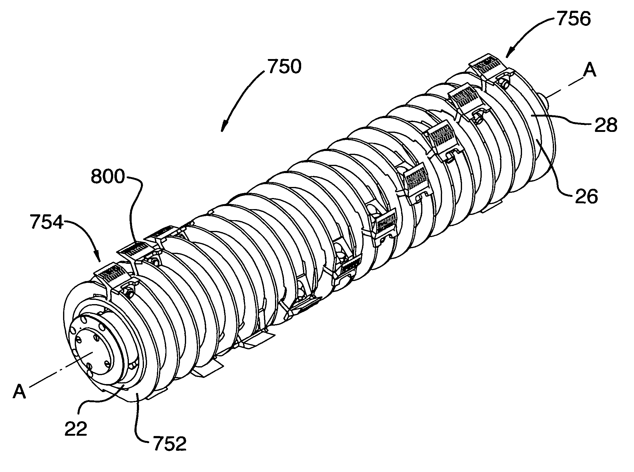
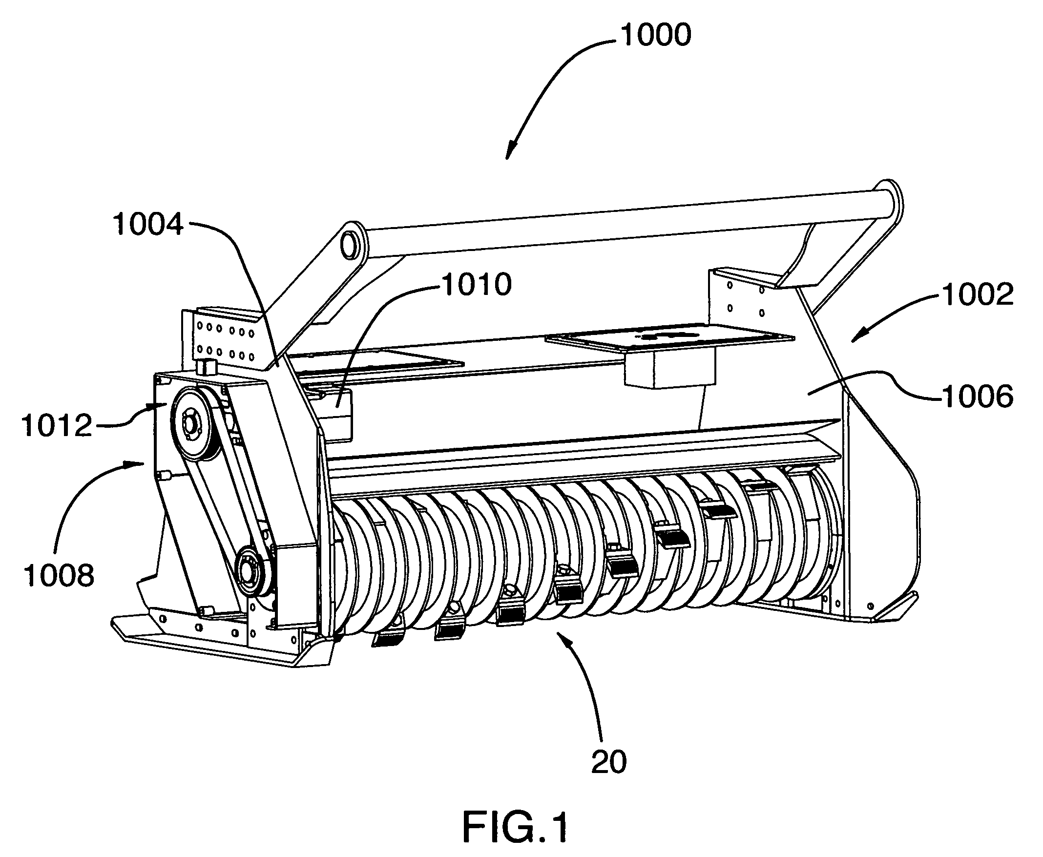
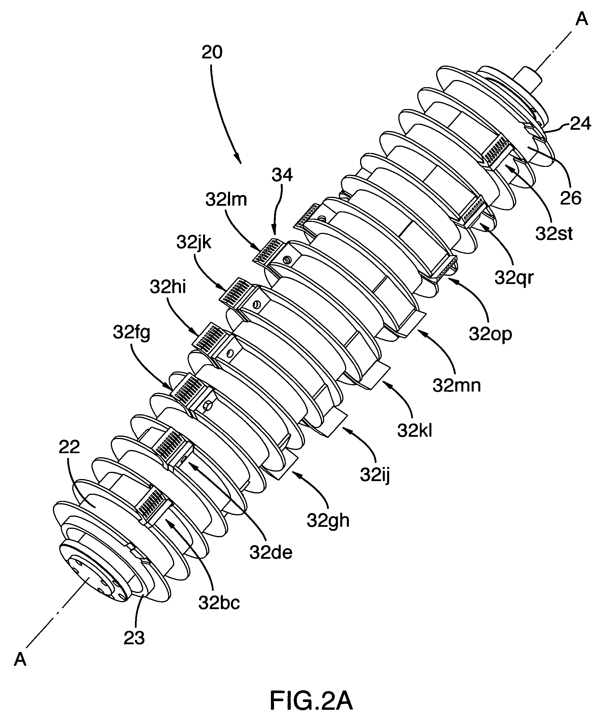
[0087]Referring to FIGS. 1, 2a and 2b, there is shown a brush cutting head generally designated with reference numeral 20. Brush cutting head 20 is adapted for use in a conventional brush cutter 1000. The brush cutter 1000 is of the type generally known to those skilled in the art such that only a very general description thereof is required for the purposes of this specification. The brush cutter 1000 may be of the type attached to the front of a vehicle, such as a loader, skid steer, or the like. It has a ho...


PUM


Abstract

The present invention relates to a brush cutting head for a brush cutter. The brush cutter head includes a cylindrical support body that has a first end, an opposed second end and an intermediate portion extending therebetween. The intermediate portion has a curved surface that defines the circular cross-section of the cylindrical support body. A plurality of collars is mounted to the cylindrical support body at spaced intervals along the intermediate portion. Each collar extends radially from the curved surface of the cylindrical support body. Additionally, each collar cooperates with an adjacent collar to define a mounting station between the adjacent collars. The brush cutter head further includes a plurality of cutting tooth assemblies carried on the outer surface of the cylindrical support body. Each cutting tooth assembly has a cutting tooth for placement within the mounting station and a mounting assembly engageable with the adjacent collars to secure the cutting tooth in the mounting station.

Description

FIELD OF THE INVENTION[0001]The present invention relates to a brush cutting head for a brush cutter.BACKGROUND OF THE INVENTION[0002]Vast felling and mulching operations are often performed with heavy-duty brush cutters. These brush cutters often have heavy-duty cutting heads removeably or permanently fixed on self-propelled vehicles. These cutting heads typically include a rotatable horizontal drum or roller upon which is mounted a plurality of cutting elements (i.e. cutting teeth). In operation, the rotation of the drum causes the cutting teeth to shred wood, debris and the like.[0003]The cutting teeth are typically fixed to the outer surface of the drum via mounting blocks. Different mounting block configurations presently exist. For example, U.S. Pat. No. 5,873,534 describes a cutter tooth holder assembly for mounting about the curved surface of a rotatable cutter drum. The cutter tooth holder assembly includes a tooth holder for holding a cutter tooth and a mounting plate for ...

Claims


Application Information

Patent Timeline
Patent Type & Authority Patents(United States)
IPC IPC(8): B27C1/00B27G13/00
CPCA01G23/00B02C18/184Y10T407/1958Y10T407/1936
Inventor LABBE, ETIENNE
Owner GYRO TRAC
Learn More