
Error conceal device and error conceal method

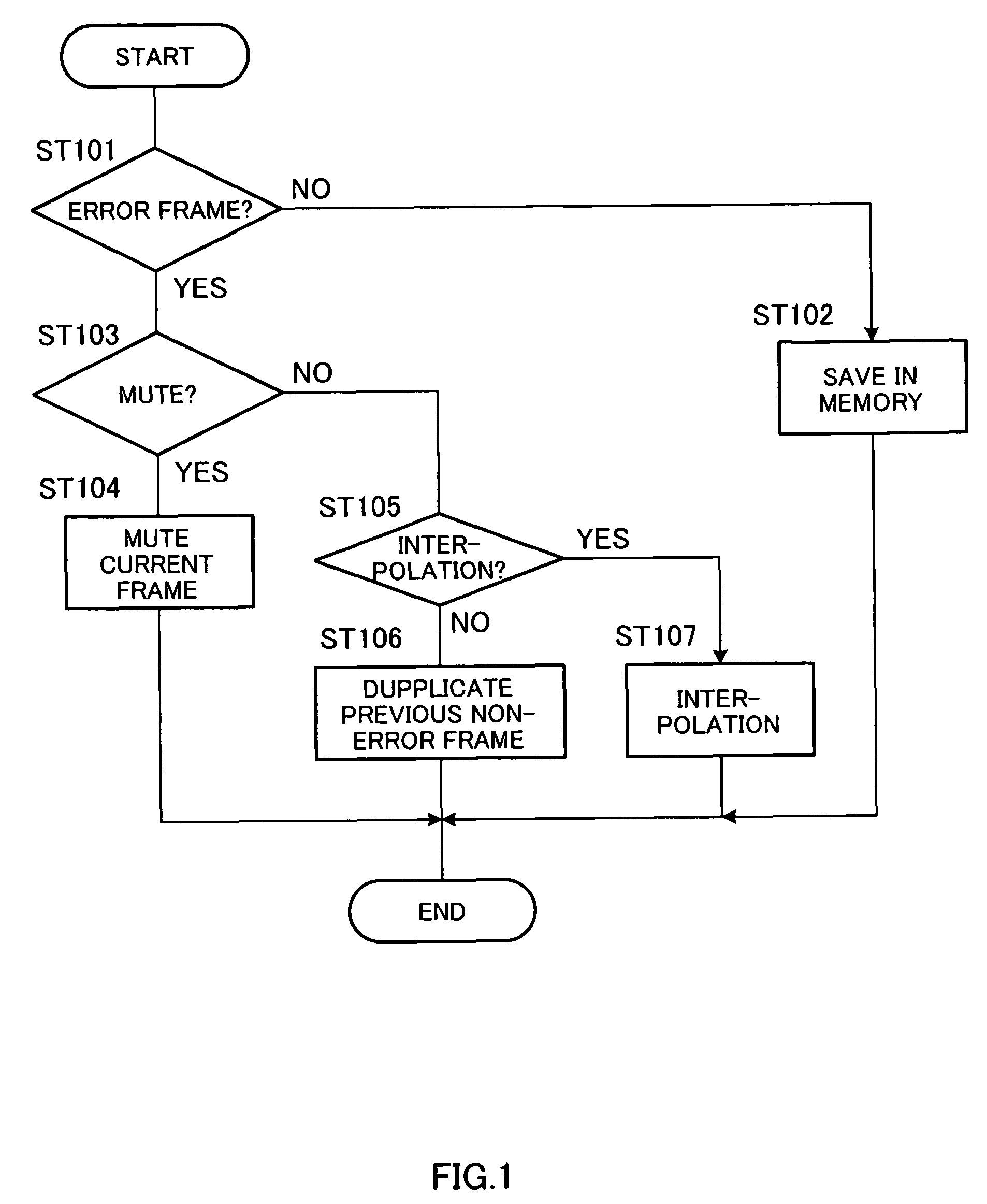
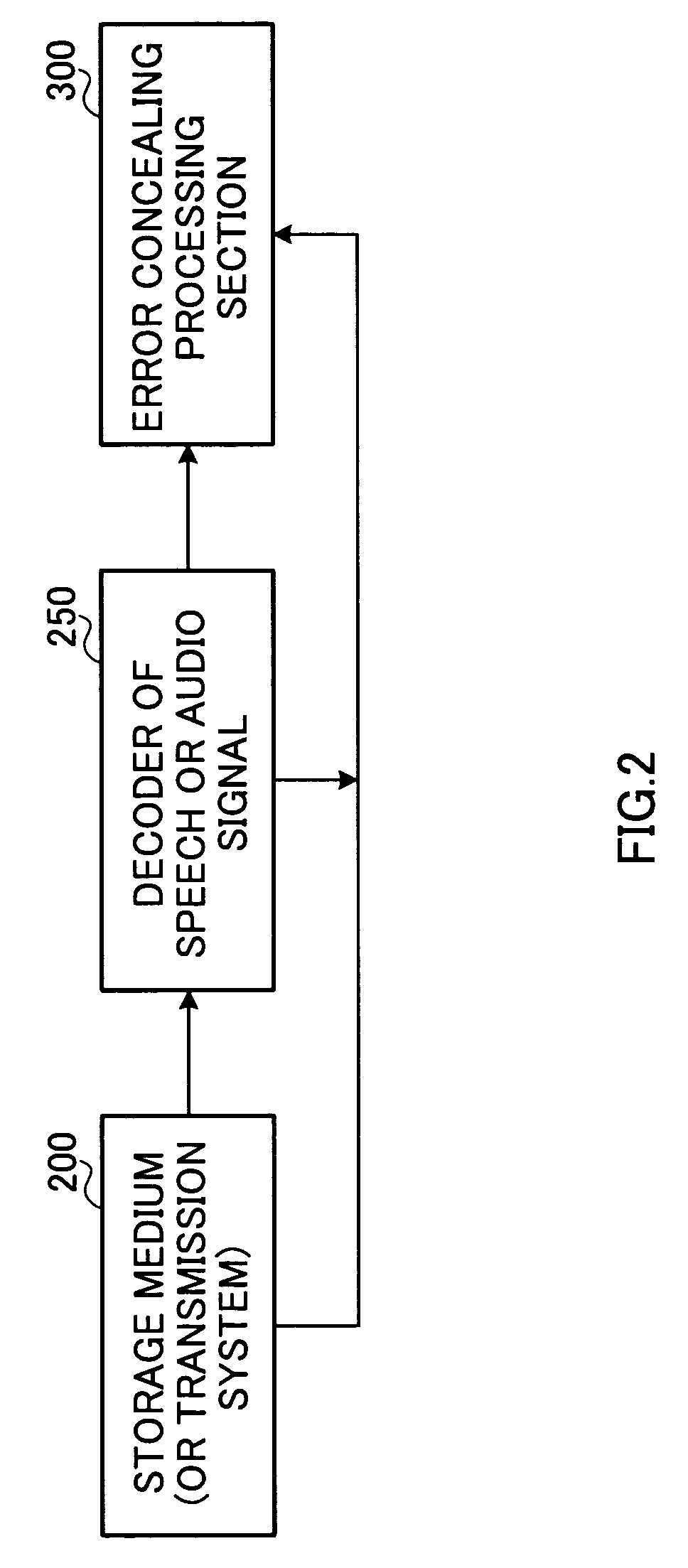
a conceal device and error concealing technology, applied in the field of error concealing devices and error concealing methods, can solve the problems of loss or corruption of packages, inability to completely avoid losses, audible artifacts, etc., and achieve the effect of concealing lost or corrupted frames

Active Publication Date: 2010-10-05
PANASONIC INTELLECTUAL PROPERTY CORP OF AMERICA
View PDF22 Cites 38 Cited by
  • Summary
  • Abstract
  • Description
  • Claims
  • Application Information

AI Technical Summary

Benefits of technology

[0025]According to the present invention, it is possible to effectively conceal lost or corrupted frames.

Problems solved by technology

When transmitting information packets or frames, whether by way of wired or wireless means, some of these packets may be lost or get corrupted.
Even with the increase of bandwidth and improvement of network or transmission technologies, such losses cannot be completely avoided.
In the case where a speech packet or audio packet is lost or get corrupted, such loss or corruption may result in audible artifacts, degrading of audio quality and unperceptive audio content.
The degradation is especially annoying during real-time streaming or transmission.
Furthermore, there are more complex methods, which are codec dependent in that it is optimized for a particular type of speech or audio codec.

Method used


Image

  • Error conceal device and error conceal method
  • Error conceal device and error conceal method
  • Error conceal device and error conceal method

Examples


embodiment 1

[0037]First, a main framework will be explained. FIG. 5 is a flow chart showing detailed steps of an error concealment algorithm according to Embodiment 1. A received frame is classified as non-error frame, error frame as speech or error frame as audio.

[0038]A non-error frame will be processed as follows.

[0039]In ST501, it is detected whether a received audio frame is an error frame or non-error frame. When a non-error frame is received, the frame is stored in a memory in ST513 so that it can be used when an error frame is received in the future. This memory has a first-in first-out (FIFO) structure and can store n frames of past audio samples. A standard size of the memory can be set to 2 frames and the most recent past two frames of a sample are stored in the memory. When a new audio frame arrives, the oldest frame out of the n frames in the memory is discarded and the new frame is concatenated to the remaining frames in the memory. Next, in ST512, an error flag of a current frame...


PUM


Abstract

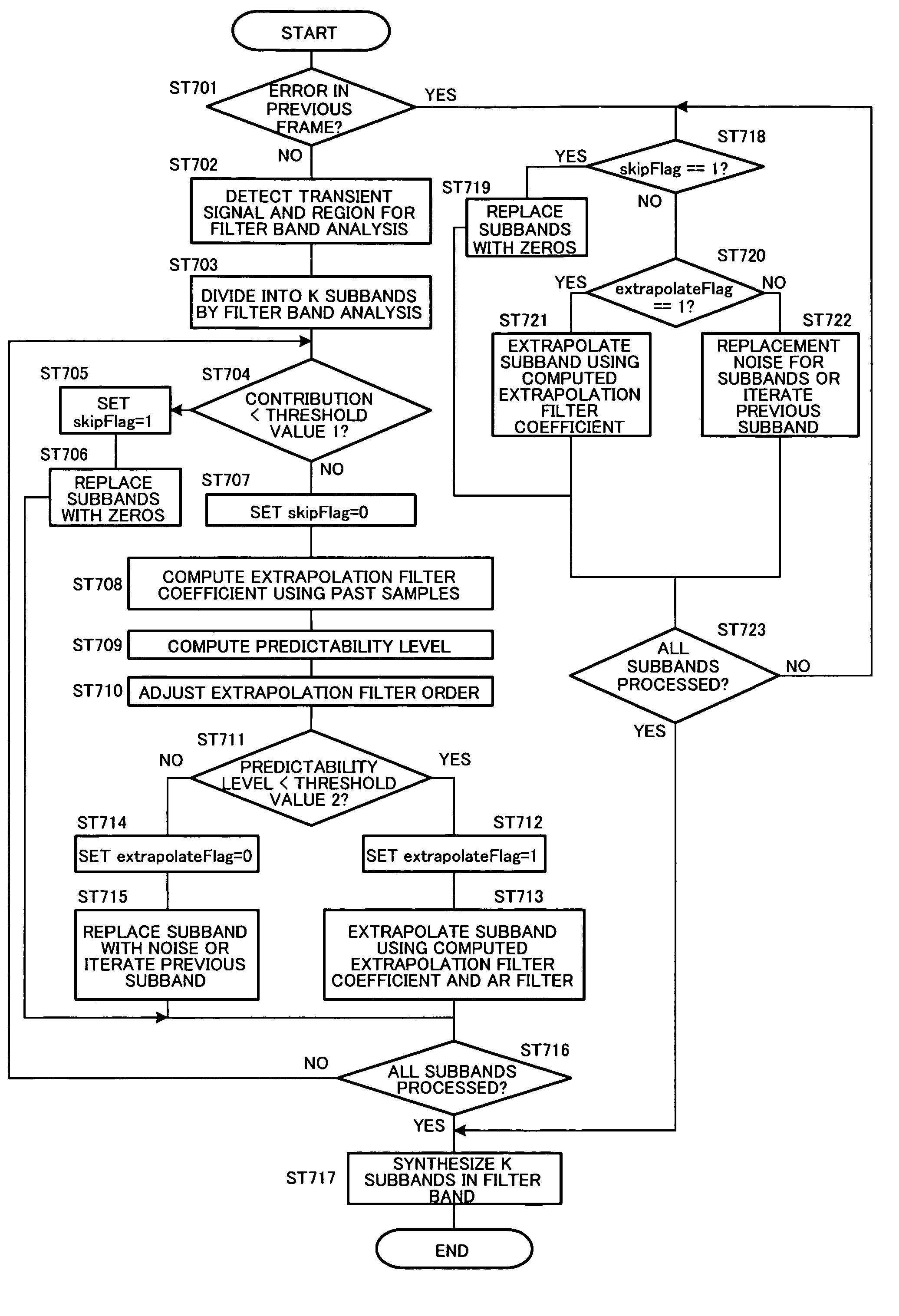
The conventional error conceal processing generates a greatly fluctuating irregular sound which is unpleasant to ears and causes a remarkable echo effect and click noise. A notification signal detection unit (301) judges processing for an input frame. In case of an error frame, a sound detection unit (303) makes judgment whether a preceding non-error data frame is a sound signal. If it is a sound frame, a sound copying unit (304) generates a replacing frame. If it is a non-sound frame, a transient signal detection unit (305) judges whether it is an attack signal by the transient signal detection and selects an appropriate area from the preceding non-error frame.

Description

TECHNICAL FIELD[0001]The present invention relates to a technology for concealing lost or corrupted digital audio signals (errors) in the area of transmission, delivery and storage medium.BACKGROUND ART[0002]When transmitting information packets or frames, whether by way of wired or wireless means, some of these packets may be lost or get corrupted. Even with the increase of bandwidth and improvement of network or transmission technologies, such losses cannot be completely avoided.[0003]In the case where a speech packet or audio packet is lost or get corrupted, such loss or corruption may result in audible artifacts, degrading of audio quality and unperceptive audio content. The degradation is especially annoying during real-time streaming or transmission.[0004]In order to minimize such degradation, error concealment scheme is employed. The fundamental idea is to replace the error data with some synthesis or generated data. The purpose of error concealment, as the name implies, is t...

Claims


Application Information

Patent Timeline
Patent Type & Authority Patents(United States)
IPC IPC(8): G10L19/10G10L19/005G10L25/87H03M7/30H04L1/00
CPCG10L19/005H04L1/0045H04L1/0061G10L25/78
Inventor GOTO, MICHIYOTEO, CHUN WOEINEO, SUA HONGYOSHIDA, KOJI
Owner PANASONIC INTELLECTUAL PROPERTY CORP OF AMERICA
Learn More