
Industrial robot

a robot and industrial technology, applied in the field of industrial robots, can solve the problems of increasing the mass of the joint, the cost of the robot is wholly high, and the size of the joint portion, etc., and achieves the effects of simple structure, easy to correspond, and low cos

Active Publication Date: 2010-10-05
PANASONIC CORP
View PDF10 Cites 17 Cited by
  • Summary
  • Abstract
  • Description
  • Claims
  • Application Information

AI Technical Summary

Benefits of technology

[0008]The present invention is made in view of the conventional problem mentioned above, and the present invention provides a waterproof and dustproof structure of a joint portion of a robot which is inexpensive and does not adversely affect a motion performance of the robot.
[0010]In accordance with this structure, it is possible to achieve a joint portion structure which is inexpensive and compact in size and has a dustproof and waterproof characteristic, by applying a dustproof and waterproof treatment only to the cable through hole portion provided in the side surface of the manipulator.
[0011]Further, even in the case where a quantity and a magnitude of the cable and the fluid conduit pipe or the like for supplying air, gas or the like is modified in accordance with a specification change of the motor driving each of the joint axes of the robot and the welding feeding apparatus, the various sensor devices and the like mounted on the robot, it is possible to easily correspond thereto without affecting the power transmitting parts or the like arranged on the joint axis.
[0012]As mentioned above, in accordance with the present invention, it is possible to achieve the dustproof and waterproof structure of the joint portion of the manipulator in the very simple structure. Further, it is possible to easily correspond also to the modification of the cable, the fluid conduit pipe and the like without exerting an influence such as the shape modification on the power transmitting parts or the like.

Problems solved by technology

Accordingly, power transmitting parts such as a pulley, a timing belt and the like and a bearing mechanism are increased, and it is unavoidable that a cost of the robot becomes wholly high.
Further, since the structure of the joint portion is complicated, the joint portion is enlarged in size and a mass thereof is increased.

Method used


Image

  • Industrial robot
  • Industrial robot
  • Industrial robot

Examples


embodiment

[0032]A description will be given below of an embodiment in accordance with the present invention with reference to FIGS. 1 to 4.

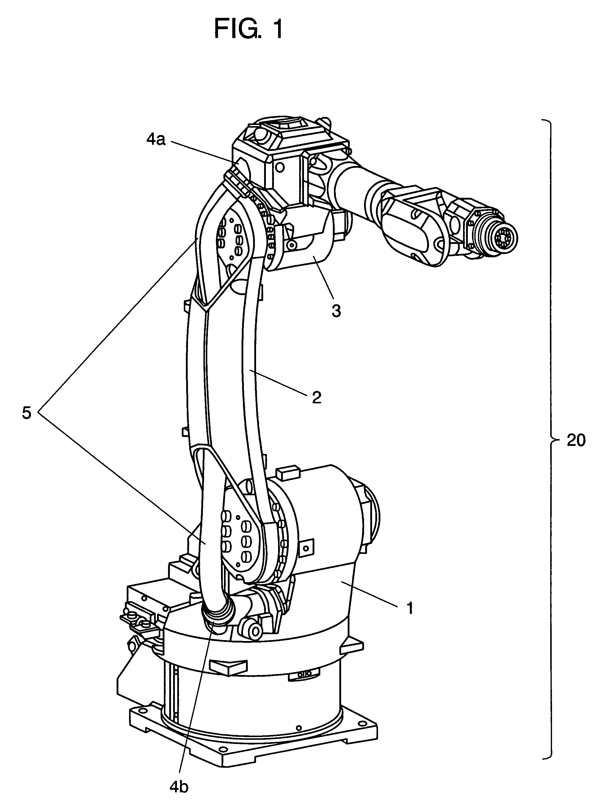
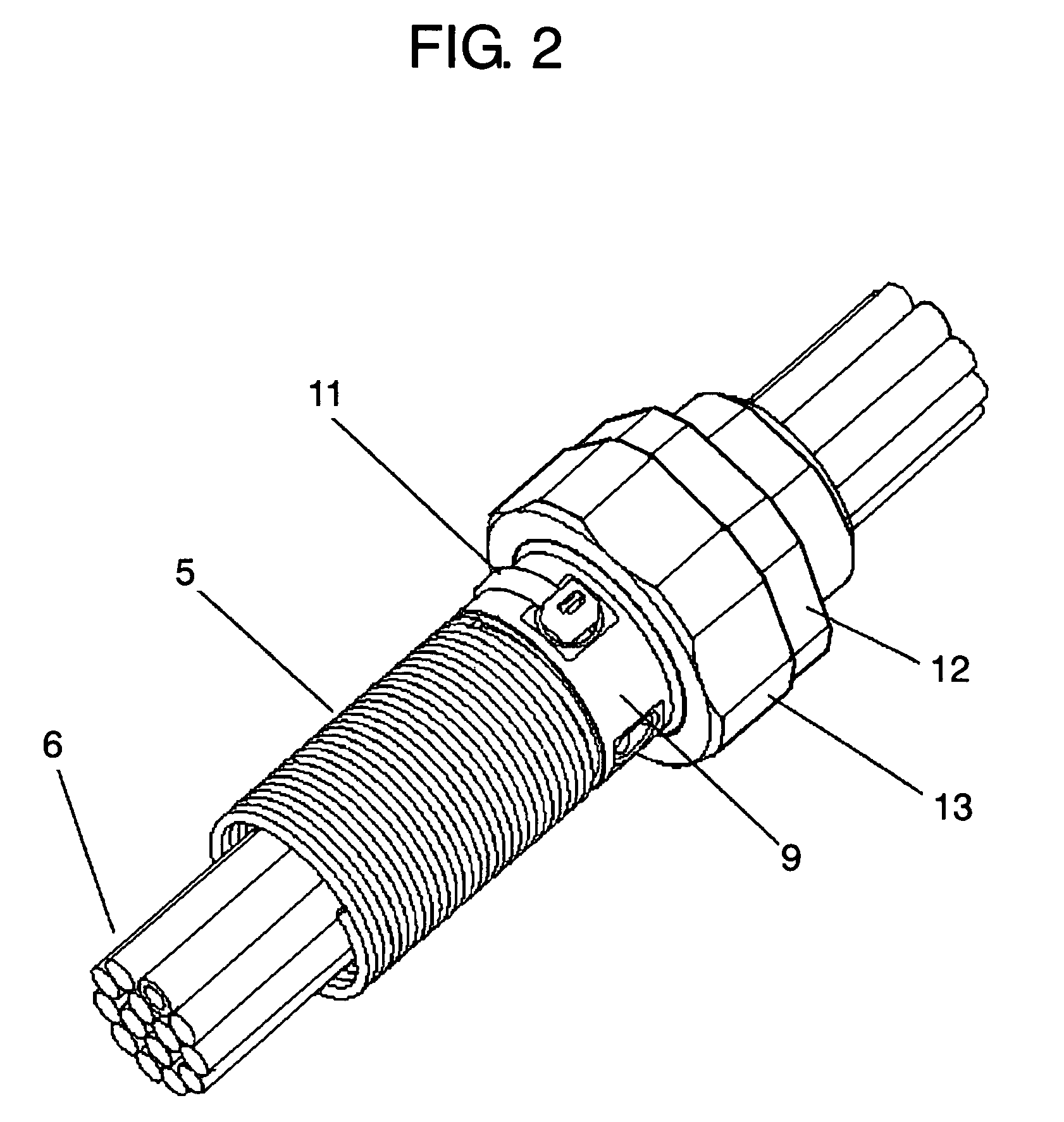
[0033]FIG. 1 is a perspective view showing an outline structure of an industrial robot in accordance with the present embodiment. FIG. 2 is a perspective view of a main portion showing an outline structure of a dustproof and waterproof structure of a robot joint portion, and FIG. 3 is an exploded view of the main portion showing the outline structure of the dustproof and waterproof structure of the joint portion.

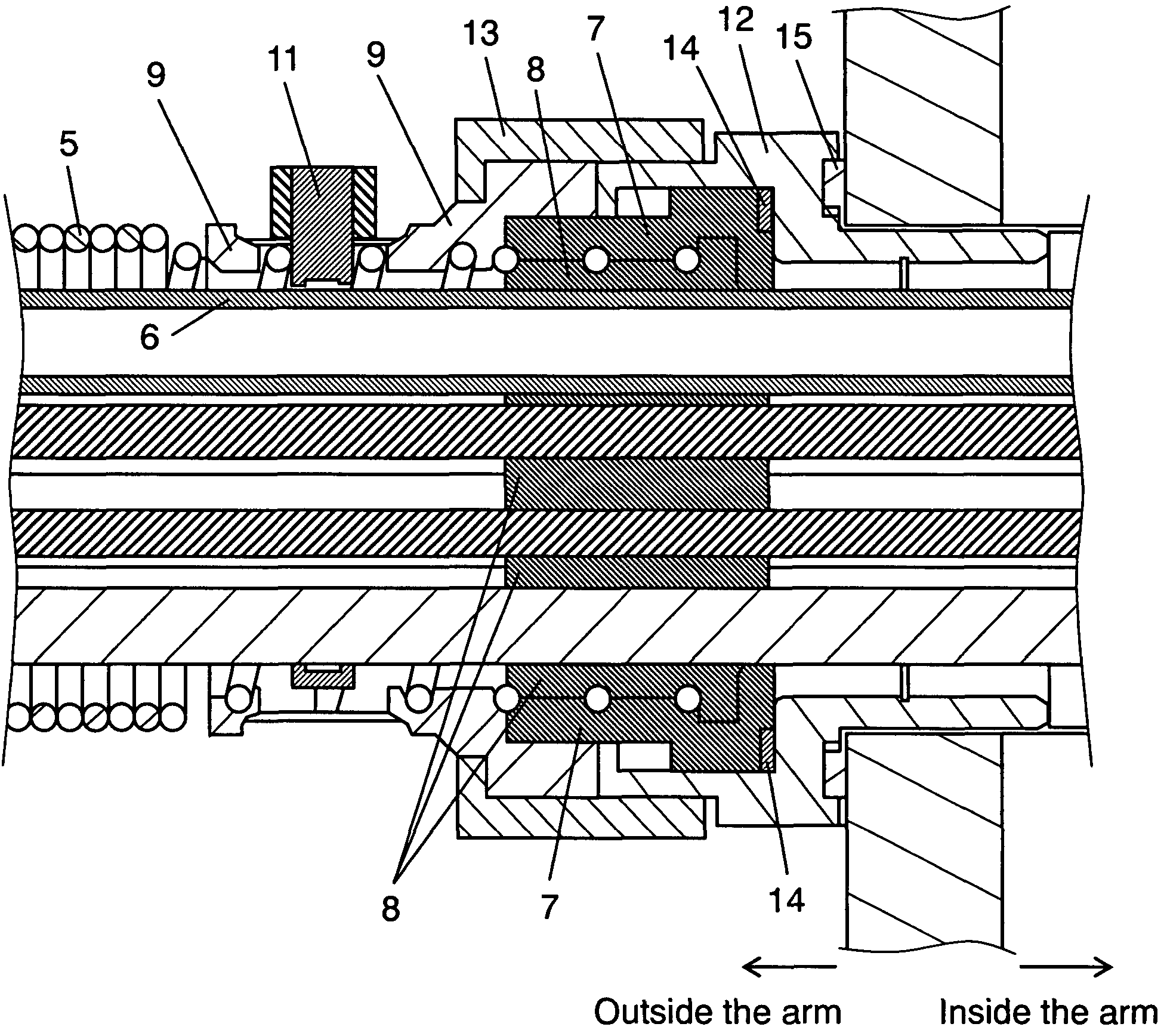
[0034]FIG. 4 is a cross sectional view of a main portion showing the dustproof and waterproof structure near cable passing holes 4a and 4b provided near the joint portion.

[0035]As shown in FIG. 1, the robot is provided with first arm 1, second arm 2 and third arm 3 in manipulator 20.

[0036]Cable passing holes 4a and 4b are provided near a joint portion of an outer periphery (an outer surface) of manipulator 20, and thread portions (not shown) are pr...


PUM


Abstract

The invention provides a waterproof and dustproof structure of a joint portion of an industrial robot which is inexpensive and does not adversely affect a motion performance of a robot. Accordingly, in a manipulator type robot which has a cable passing hole provided in a part of an outer periphery of a manipulator, and is provided with a cable wired to an inner side and an outer side of the manipulator through the cable passing hole, a mold guide surrounding an outer periphery of one or a plurality of conducting wire passing through an inner portion is provided near the cable passing hole, an inner side of the mold guide is mold treated by a resin filling, and a sealing material is provided in an outer side of the mold guide.

Description

TECHNICAL FIELD[0001]The present invention relates to an industrial robot, and more particularly to a dustproof and waterproof structure of an inside wiring cable in a joint portion of the industrial robot.BACKGROUND ART[0002]Generally, in an industrial robot (hereinafter, refer to as “robot” in an abbreviating manner), there is wired various filament bodies such as an electric cable used in a motor driving each of joint axes of a robot and a welding feeding apparatus and various sensor devices mounted on the robot, a fluid conduit pipe for supplying an air, a gas or the like, and the like.[0003]Further, these wiring filament bodies have such a constraint condition as a radius of bending and a rotational motion range taking a mechanical durability into consideration, caused by being exposed to a bending motion and a twisting motion at a time when the joint portion of the robot executes a rotational motion, and it is necessary to take into consideration the dustproof and waterproof s...

Claims


Application Information

Patent Timeline
Patent Type & Authority Patents(United States)
IPC IPC(8): B25J19/00H02G3/22
CPCB25J19/0025B25J19/0075H02G3/22Y10T74/20311Y10S414/131
Inventor IWAI, SEIJISUZUKI, SHIAKI
Owner PANASONIC CORP
Learn More