
Selectivity enhancement in photoacoustic gas analysis via phase-sensitive detection at high modulation frequency

a technology of phase-sensitive detection and photoacoustic gas, which is applied in the field of selective enhancement of photoacoustic gas analysis via phase-sensitive detection at high modulation frequency, can solve the problems of no way to identify the spectrum, difficult or even impossible to measure or detect the presence of one of the species using pas, and the expansion or contraction of materials within the environment. , to achieve the effect of great precision

Inactive Publication Date: 2010-10-05
RICE UNIV
View PDF3 Cites 19 Cited by
  • Summary
  • Abstract
  • Description
  • Claims
  • Application Information

AI Technical Summary

Benefits of technology

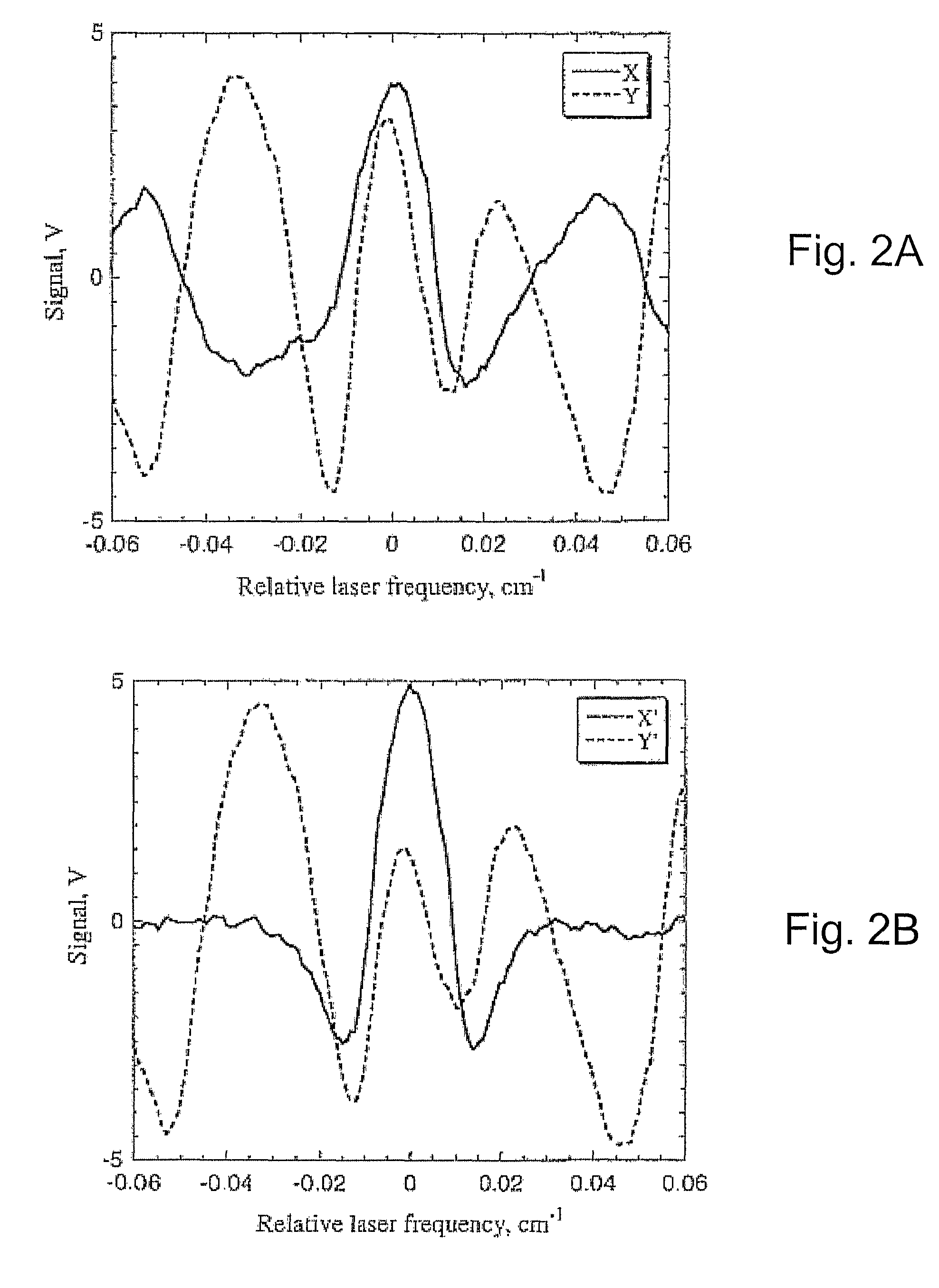
[0009]In one embodiment of the present invention, the measured acoustic signal is rotated in phase so as to suppress the signal generated by the interfering species and thereby allow detection of a signal from the target species. In some embodiments, the system is used to detect small amounts of one fluid, the target fluid or “impurity,” in a large quantity of a primary species, the “background” species. Either the primary species or the impurity may comprise more than one chemical species. In other embodiments the phase rotation is used to suppress the signal from the interfering species so that small signals resulting from the target fluid or impurity can be measured with great precision. Alternatively, the system can be used to monitor relative amounts of two fluids in a fluid sample or stream.

Problems solved by technology

Such forms of energy cause expansion or contraction of materials within the environment.
In other instances, however, such as when the sample contains more than one molecular species with overlapping absorption spectra, it is difficult or even impossible to measure or detect the presence of one of the species using PAS.
When the two (or more) spectra are overlaid, there is no way to identify the spectrum attributable to each species in the resulting spectrum.

Method used


Image

  • Selectivity enhancement in photoacoustic gas analysis via phase-sensitive detection at high modulation frequency
  • Selectivity enhancement in photoacoustic gas analysis via phase-sensitive detection at high modulation frequency
  • Selectivity enhancement in photoacoustic gas analysis via phase-sensitive detection at high modulation frequency

Examples


Embodiment Construction

Apparatus

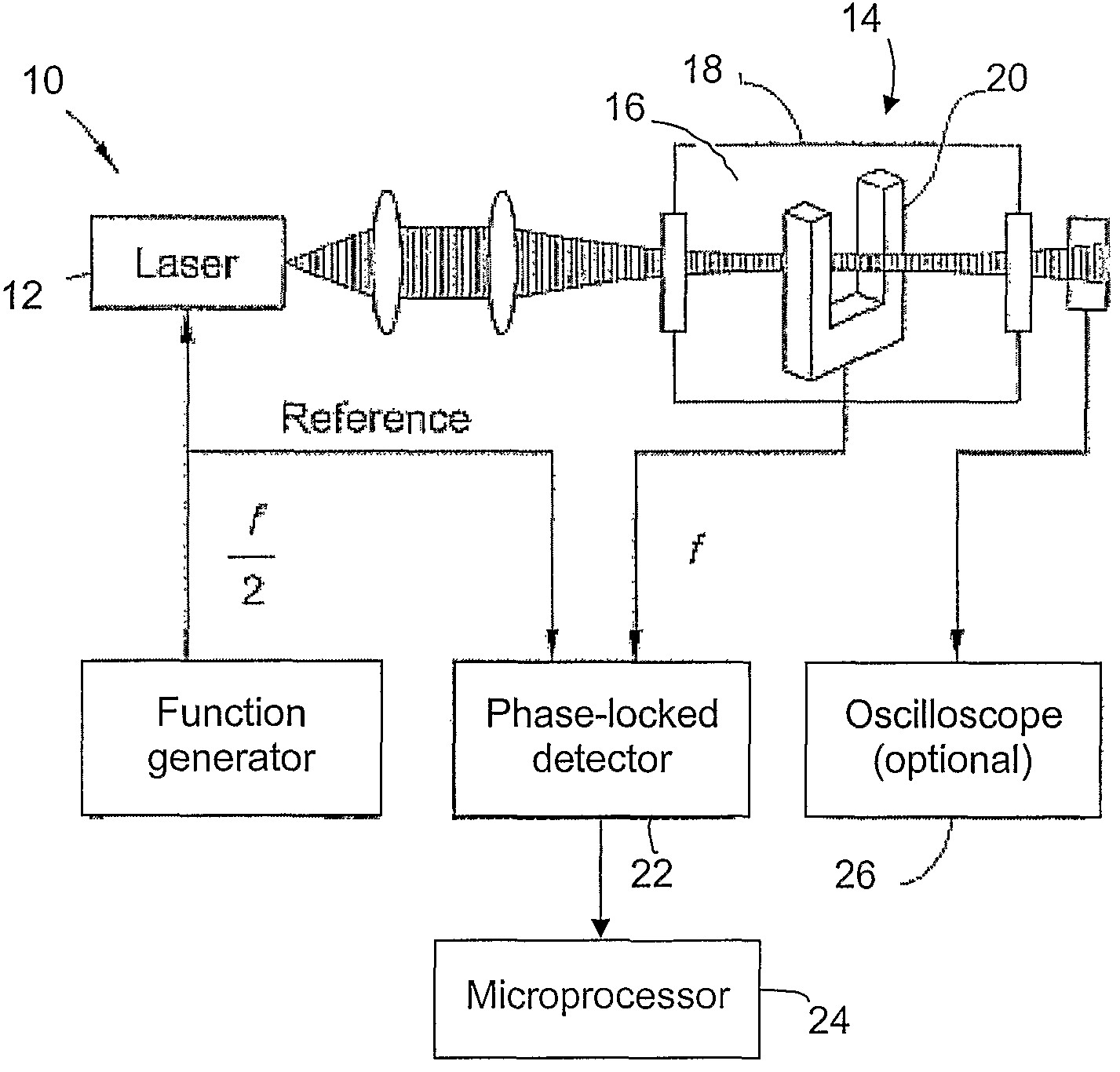
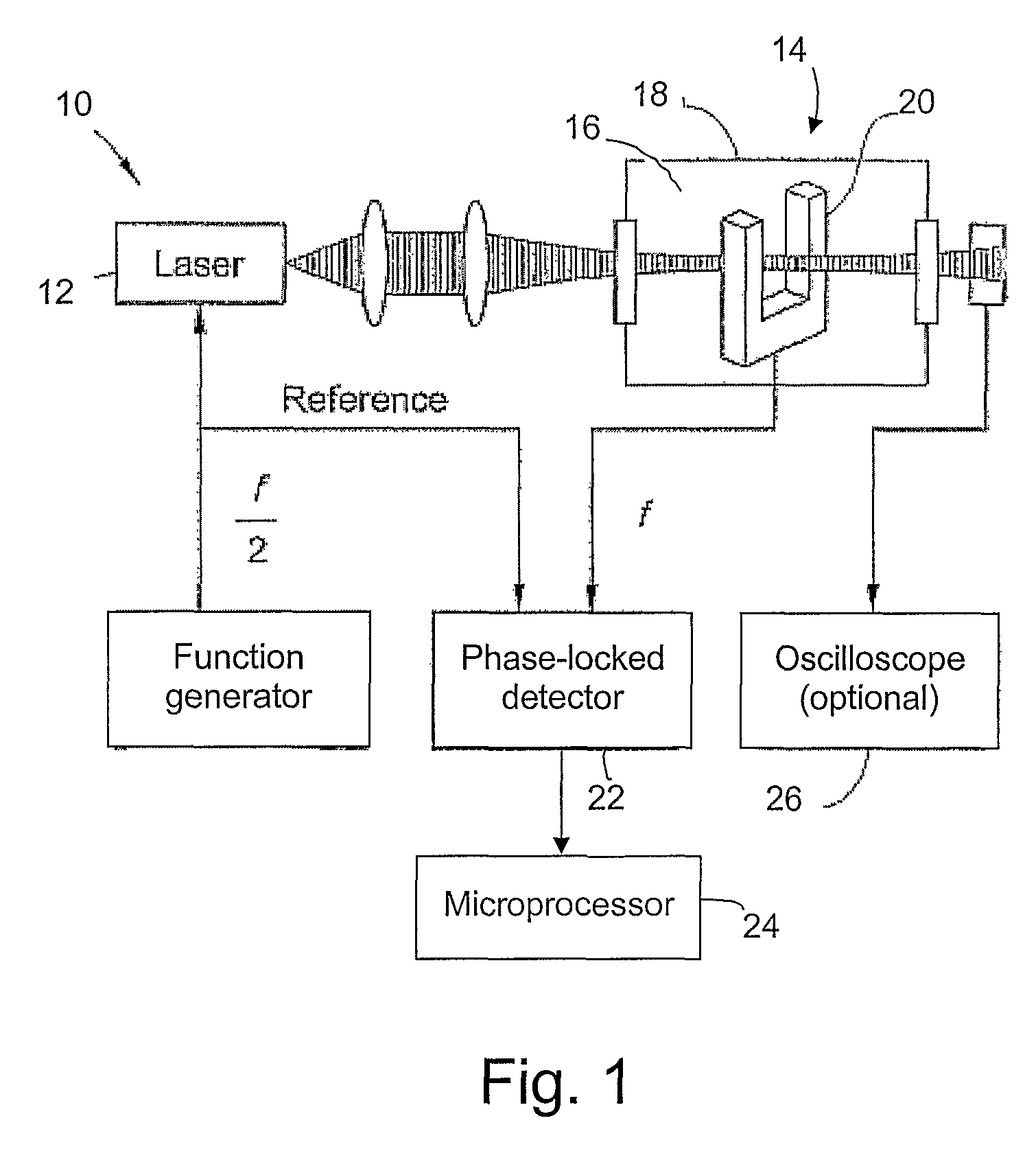
[0014]To carry out the present invention, a photoacoustic spectroscopy cell is configured to apply a modulated light signal to a sample and to detect the resulting acoustic signal using a phase-locked detector. By way of example, reference is made to FIG. 1, in which a photoacoustic apparatus 10 comprises a light source 12 configured to emit a beam of radiation into a sample holder 14. Light source 12 can comprise, for example, a laser. Filters (not shown) may be provided between light source 12 and sample holder 14 if desired.

[0015]Sample holder 14 includes a sample cell 18 containing a sample 16. Sample cell 18 can comprise a number of materials known to persons of ordinary skill in the art, and preferably comprises a material substantially transparent to the wavelength(s) of light emanating from light source 12. Preferred materials for sample cell 18 will accordingly vary depending on the wavelengths of light utilized in the spectroscopic apparatus.

[0016]Sample 16 may be...


PUM

PropertyMeasurementUnit
modulation frequencyaaaaaaaaaa
photoacoustic spectroscopyaaaaaaaaaa

Abstract

A method for detecting a target fluid in a fluid sample comprising a first fluid and the target fluid using photoacoustic spectroscopy (PAS), comprises a) providing a light source configured to introduce an optical signal having at least one wavelength into the fluid sample; b) modulating the optical signal at a desired modulation frequency such that the optical signal generates an acoustic signal in the fluid sample; c) measuring the acoustic signal in a resonant acoustic detector; and d) using the phase of the acoustic signal to detect the presence of the target fluid.

Description

STATEMENT REGARDING FEDERALLY SPONSORED RESEARCH OR DEVELOPMENT[0001]This invention was made with government support under grant number NAG9-01482 awarded by the NASA Johnson Space Center. The government has certain rights in the invention.TECHNICAL FIELD OF THE INVENTION[0002]The present invention provides a new spectroscopic method for distinguishing molecular species having overlapping absorption spectra using photoacoustic spectroscopy.BACKGROUND OF THE INVENTION[0003]Photoacoustic spectroscopy (PAS) is an analytical method that involves stimulating a sample with modulated light and detecting the resulting sound waves emanating from the sample. A photoacoustic measurement can be made as follows. First, light is used to stimulate molecules within a sample. Such stimulation can include, for example, absorption of the light by the molecule to change an energy state of the molecule. As a result, the stimulated molecule enters an excited state. Optical excitation is followed by the e...

Claims


Application Information

Patent Timeline
Patent Type & Authority Patents(United States)
IPC IPC(8): G01N21/00G01N21/17
CPCG01N21/1702G01N29/2425G01N2021/1704G01N2021/1708G01N2291/0427
Inventor KOSTEREV, ANATOLIY
Owner RICE UNIV
Learn More