
Scanning units and image reading devices

a scanning unit and image technology, applied in the field of scanning units and image reading devices, can solve the problems of unattained dramatic effects, and achieve the effects of reducing the external dimension of the carriage sliding direction, and reducing the size of the scanning uni

Active Publication Date: 2010-09-28
BROTHER KOGYO KK
View PDF4 Cites 11 Cited by
  • Summary
  • Abstract
  • Description
  • Claims
  • Application Information

AI Technical Summary

Benefits of technology

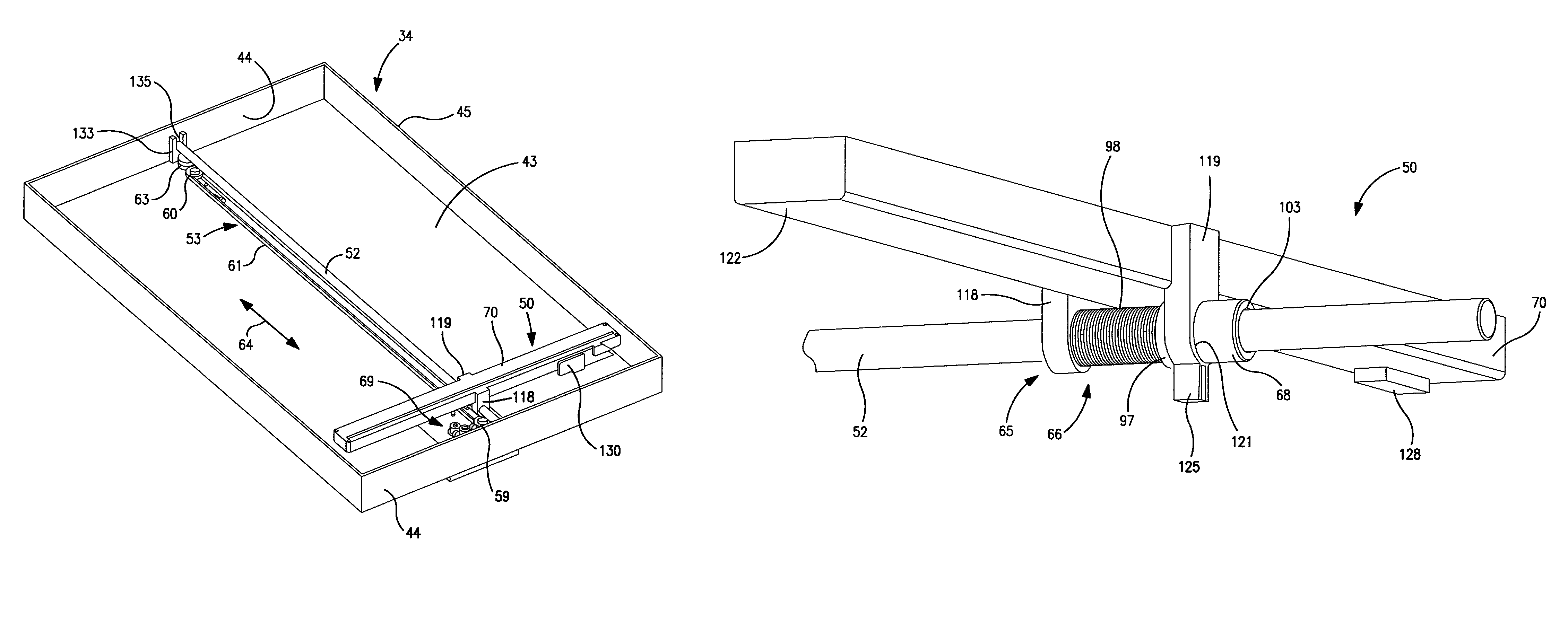
[0008]A need has arisen to provide image reading devices which are of sufficiently reduced size and weight and which also allows higher-precision image reading. It is a technical feature of such devices that they may include an image sensor unit that is used therein, as well as a scanning unit. It is an advantage of the present invention that the scanning unit may be supported over a broader region on the guide shaft when an image is being read, and, thus, higher-precision image reading may be achieved while controlling the inclination of the carriage. In addition, because the external dimensions of the carriage may be decreased during image reading standby and at other desired times, it is possible to achieve a reduction in the size and the weight of the scanning unit, as well as the image reading device that employs the scanning unit.
[0009]In order to satisfy the aforementioned need, the scanning unit of the present invention may be a scanning unit that slides along a guide shaft that runs in a predetermined direction, and has a carriage that slides along the aforementioned guide shaft, a bearing provided on the carriage through which the aforementioned guide shaft passes and an elastic deformation allowance mechanism that allows elastic deformation of the external shape of the bearing in the aforementioned predetermined direction at the predetermined time.
[0010]The scanning unit moves along the aforementioned guide shaft along with the carriage. The guide shaft passes through the bearing provided on the carriage, and this bearing elastically deforms in the predetermined direction. In other words, the external dimension of the carriage changes in the predetermined direction or in the direction of sliding. Consequently, when the external size of the bearing is increased, the carriage may slide while restricting inclination because the aforementioned guide shaft inserts into said bearing over a broader region. When the external size of the bearing is reduced, on the other hand, the external dimension in the carriage sliding direction is decreased, and, thus, the size of the scanning unit is decreased.
[0011]The aforementioned bearing preferably has a bearing ring that may slide in the aforementioned predetermined direction and through which the aforementioned guide shaft may pass. Preferably, the aforementioned elastic deformation allowance mechanism has an urging member that elastically urges the aforementioned bearing ring, so that the bearing ring protrudes beyond the external wall surface of the aforementioned carriage.
[0012]In this configuration, the guide shaft is supported on a bearing, and, thus, the structure of the bearing is simplified. The external size of the aforementioned bearing increases as a result of the elastic urging of the bearing ring outwards beyond the external wall surface of the carriage, and the external size of the aforementioned bearing decreases when the bearing ring is made to slide against the elastic force counter to the outwards-urging direction. In this manner, the elastic deformation of the bearing is dramatically simplified by providing the urging member.
[0013]It is preferable for a contact image sensor to be mounted on the aforementioned carriage. By this means, the scanning unit may be effectively reduced in weight and size. Preferably, the aforementioned contact image sensor has a box that houses a light source and light-receiving element, and this box preferably also functions as the aforementioned carriage. By this means, the size of the carriage may be reduced, and the size and weight of the scanning unit also are decreased.

Problems solved by technology

For this reason, dramatic effects have not been attained, even though these known-types of countermeasures have been employed.

Method used


Image

  • Scanning units and image reading devices
  • Scanning units and image reading devices
  • Scanning units and image reading devices

Examples


Embodiment Construction

[0034]The invention is described in detail below based on preferred embodiments in reference to the appropriate drawings.

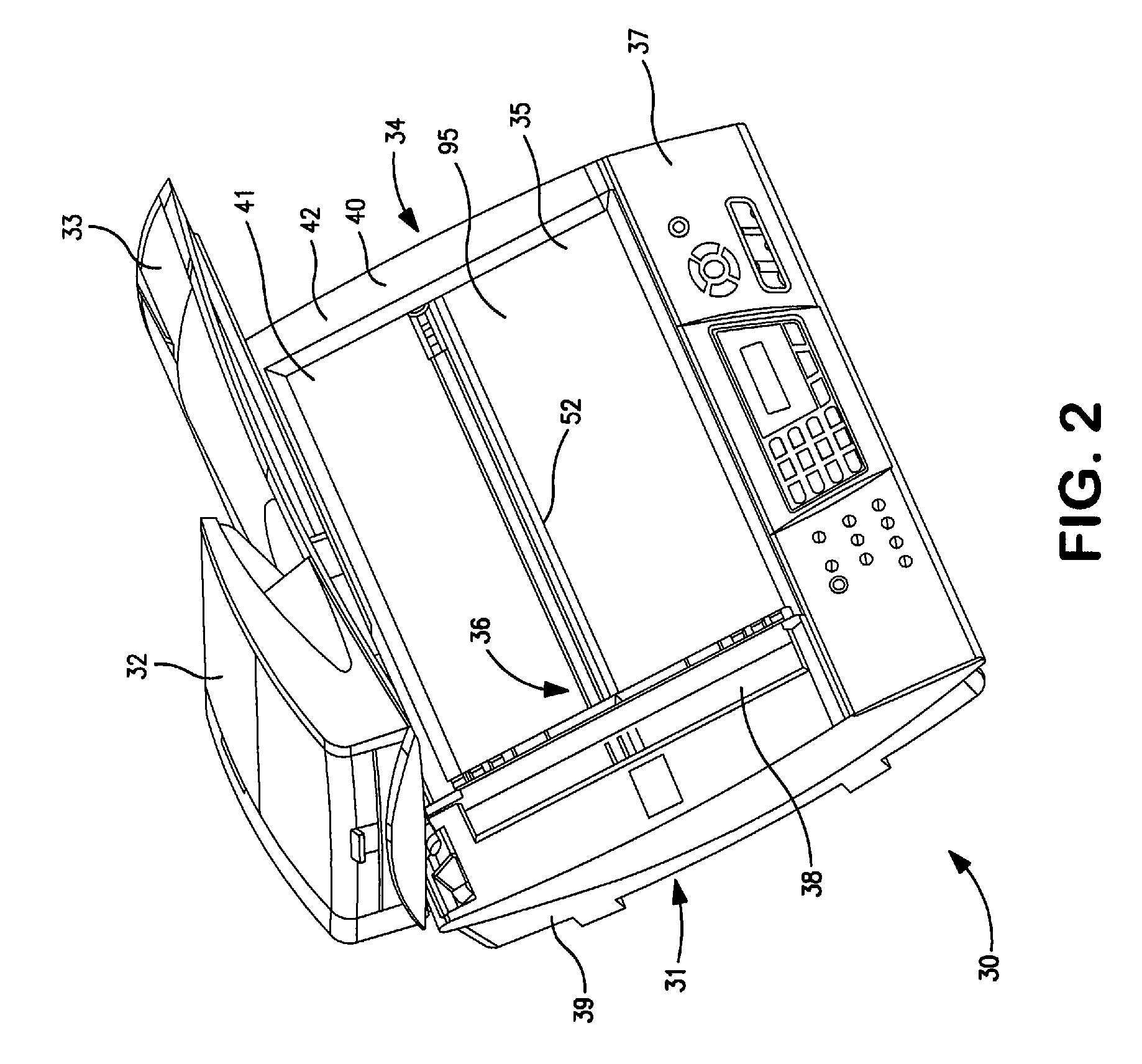
[0035]FIG. 2 is an external perspective of an image reading device 30 pertaining to an embodiment of the present invention. Image reading device 30 is used as a scanner part in a multifunctional device (“MFD”) that has an integrated printer function and scanner function. Alternatively, the device may be configured as an image reading part for copiers. Image reading device 30 also may be configured, for example, as a flat bed scanner (“FBS”) that has only a scanning function.

[0036]As shown in the drawings, image reading device 30 has a reading placement table 31 that functions as an FBS, and a document press cover 33 is attached on the reading placement table 31, so that it may be opened and closed. Document press cover 33 has an auto-document feeder (“ADF”) 32. The reading placement table 31 has a substantially square, main frame 34 (e.g., a casing), a contact gla...


PUM


Abstract

A scanning unit is configured to slide along a guide shaft that extends in a predetermined direction. The scanning unit includes a carriage configured to slide along the guide shaft, a bearing which is disposed on a carriage and through which the guide shaft passes, and an elastic deformation allowance mechanism which permits elastic deformation of the external shape of the bearing in the predetermined direction at a predetermined time. For example, a contact image sensor unit includes a box equipped with a contact image sensor. The box has a bearing through which a guide shaft is inserted. The bearing has a pair of bosses, bushings that fit therein, and a coil spring that is disposed between the bushings. The bushings are urged by the coil spring, so that the bushings continually protrude outwards. As the contact image sensor unit slides along the guide shaft, the bushings insert in between the bosses when the bushings abut the wall surface of the frame, so that the bearing is deformed elastically. An image reading device may include a scanning unit.

Description

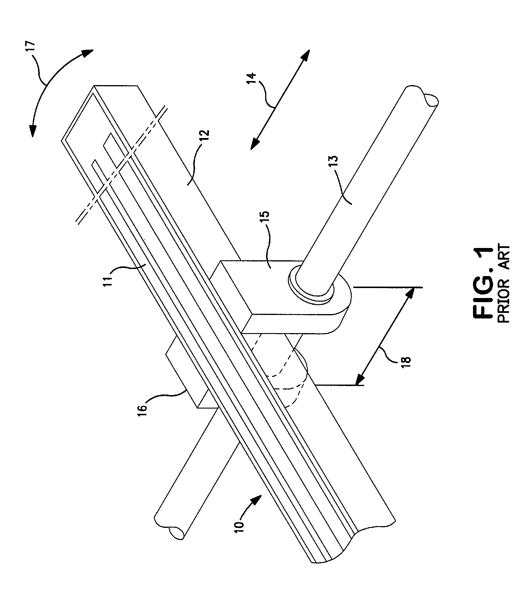
BACKGROUND OF THE INVENTION[0001]1. Field of the Invention[0002]This application claims the benefit of Japanese Patent Application No. 2005-374093, filed Dec. 27, 2005, which is incorporated herein by reference.[0003]The present invention relates to image reading devices that are used in multifunction devices (“MFDs”), and more specifically relates to the structures of the image sensor units used in these image reading devices.[0004]2. Description of Related Art[0005]FIG. 1 is a perspective view of significant elements of a known conventional image reading device. This image reading device has an image sensor unit 10. Image sensor unit 10 has a contact-type image sensor (“CIS”) 11 and a carriage 12 that holds contact image sensor 11. Carriage 12 is supported by a guide shaft 13 and slides in the direction indicated by arrow 14 by means of a slide device not shown in the drawings. Carriage 12 has a pair of bearings 15, 16, and guide shaft 13 is inserted or extends through bearings 15...

Claims


Application Information

Patent Timeline
Patent Type & Authority Patents(United States)
IPC IPC(8): H04N1/04
CPCH04N1/1017H04N1/1026H04N2201/0442
Inventor OSAKABE, YOSHINORI
Owner BROTHER KOGYO KK
Learn More