
Solid composition stick applicator

a technology of composition stick and stick, which is applied in the direction of rail lubrication, railway auxilary equipment, engine lubrication, etc., can solve the problems of affecting the performance of the stick, and leaving oil on the track and surrounding area, etc., and achieves the effect of improving the performan

Inactive Publication Date: 2010-09-28
KELSAN TECH
View PDF16 Cites 3 Cited by
  • Summary
  • Abstract
  • Description
  • Claims
  • Application Information

AI Technical Summary

Benefits of technology

The applicator achieves significantly longer spring life, reduced maintenance needs, and efficient lubricant delivery with a durable and lightweight design, capable of handling harsh environments and extended service intervals.

Problems solved by technology

However, these types of lubricant showed the tendency to creep onto the crown of the rail, which caused unacceptable slippage.
This technology also left oil on the track and surrounding area.
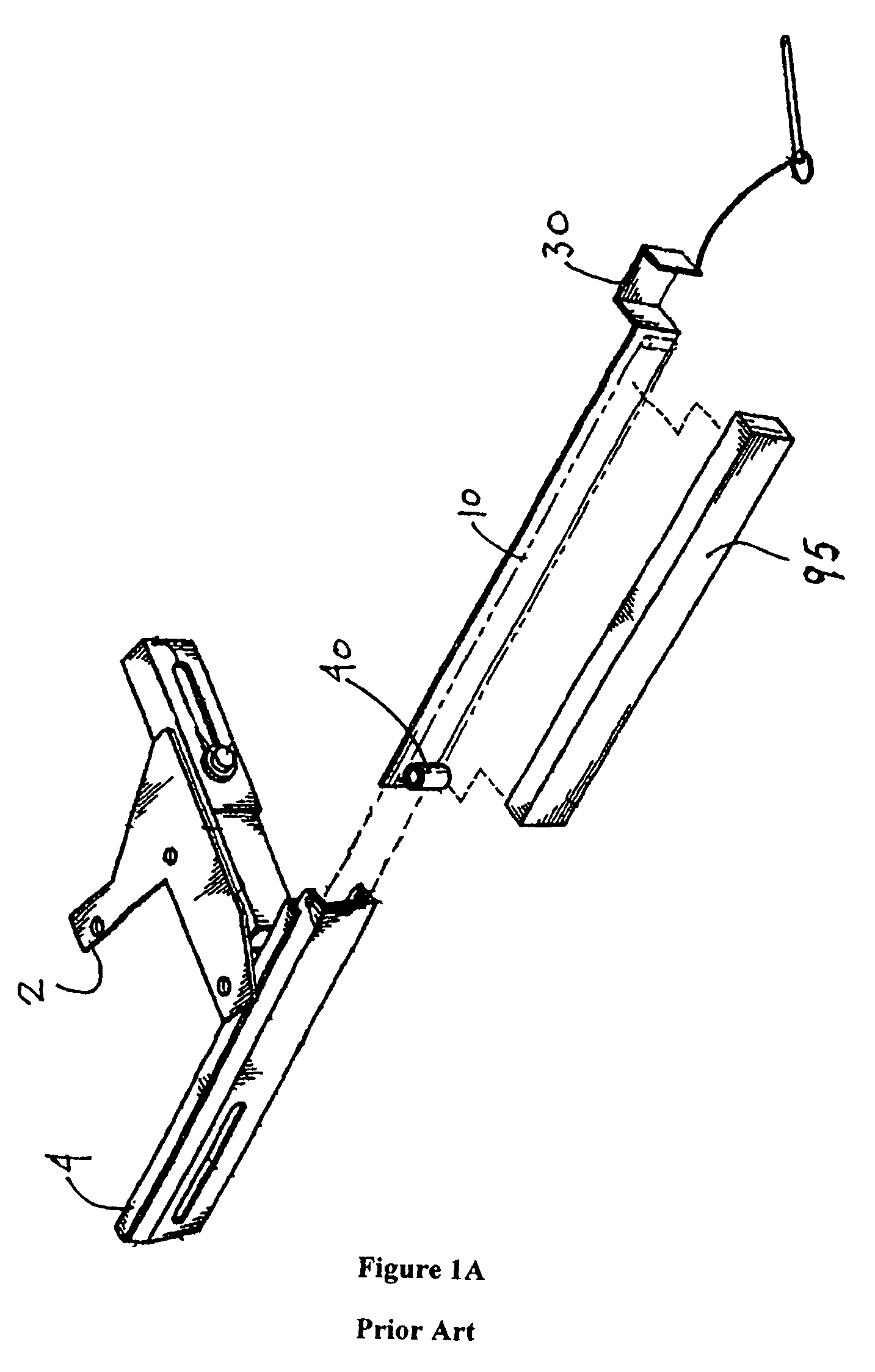
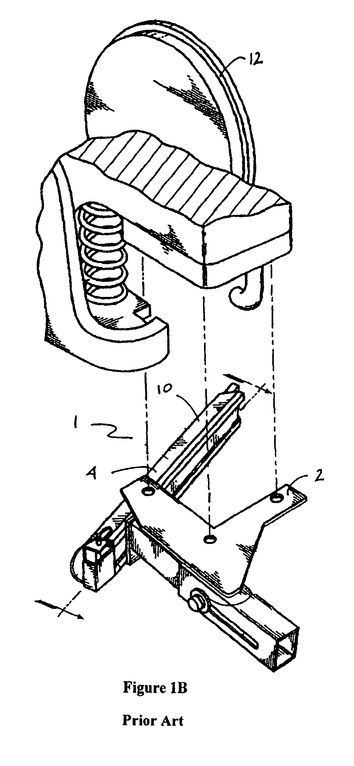
However, the lubricant or composition stick in Jamison is exposed to dust, dirt and oil present in the environment of the locomotive underside, which affects its performance.
Furthermore, in this system, lubricant or composition stick manufacture is complex, as a stud, or a recessed nut, must be inset into the upper end of the stick for attachment to the applicator.
Replacement of the stick therefore is complex.
This mechanism is easily jammed with contamination and debris during use, is difficult to maintain, and is subject to premature wear.
While the '724 and '860 applicators require less space when replacing the lubricant, the cutout results in significant contamination of the stick and the applicator and jamming may occur.
Furthermore, the coiled flat springs tend to fail prematurely, resulting in increased maintenance.
As noted above with reference to U.S. Pat. Nos. 5,251,724 and 5,337,860, these cyclical stresses cause the CFS to quickly develop fatigue cracks, resulting in short spring life.

Method used


Image

  • Solid composition stick applicator
  • Solid composition stick applicator
  • Solid composition stick applicator

Examples


examples

[0082]The applicators comprising prior art constant force springs, and helical tension springs of the present invention were tested to determine reliability and performance. A spring extension test rig (SETR; FIG. 5a) and a rotating cam test rig (RCTR; FIG. 5b) were used to simulate service conditions.

[0083]As described in more detail below, test results show that, compared to a prior art applicators comprising constant force springs, for example as disclosed in U.S. 2003 / 0,101,897; U.S. Pat. No. 5,251,724 or U.S. Pat. No. 5,337,860, the applicator and helical tension spring of the present invention exhibit substantially greater spring life. The applicator and spring assembly of the present invention provides between 19 and 46 times greater service life that an applicator comprising a CFS, when tested under the conditions. After each test, the applicator was disassembled and the moving parts examined. Wear and service life is recorded for each part. It was found that the present app...


PUM


Abstract

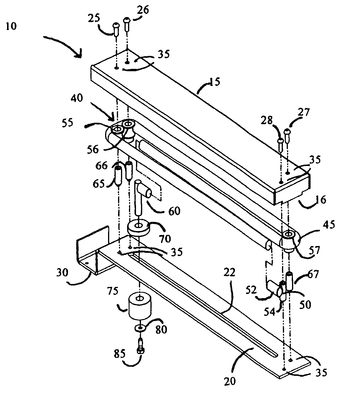
A solid composition stick applicator is provided. The applicator comprises an applicator body having a first and second end, the second end having an opening through which a solid composition stick is dispensed. Within the applicator is housed a helical tension spring having a first spring end and a second spring end, the first spring end, second spring end, or both the first and second spring end held at a fixed position with respect to the applicator body. The helical tension spring is wound around a guide system that is housed within the applicator body. A pushing assembly is attached to the helical tension spring and the pushing assembly is movable from a first position at or near the first end of the applicator body, to a second position at or near the second end of the applicator body. Tension within the helical tension spring is greater in the first position than in the second position thereby urging the pushing assembly towards the second end of the applicator body. The use of a helical tension spring within the applicator greatly increases the life of the applicator under field conditions.

Description

[0001]The present invention relates to a solid composition stick applicator, more particularly to a solid composition stick applicator having improved performance.BACKGROUND OF THE INVENTION[0002]Over the last two decades there has been a significant increase in the presence of motorized rail transportation in urban areas resulting in an increasing need for methods of reducing the high frequency sounds which result from the twisting of the axle and sudden subsequent release of the twist as a curved rail is negotiated by the wheels of a train.[0003]Initially, lubrication and noise reduction were addressed by pumping oil under pressure through nozzles directed at the wheel contact point with the track. However, these types of lubricant showed the tendency to creep onto the crown of the rail, which caused unacceptable slippage. This technology also left oil on the track and surrounding area. Due to environmental concerns caused by this oil contamination, solid stick lubricants have inc...

Claims


Application Information

Patent Timeline
Patent Type & Authority Patents(United States)
IPC IPC(8): B61K3/00
CPCB61K3/00
Inventor DE WET, JONATHANHUI, RON C. Y.MCKAY, DOUGLAS ROBERTZDJELAR, ZDRAVKOHARRIS, ROBERT J.
Owner KELSAN TECH
Learn More