
Method and device for detecting leaks

a leak detection and leakage detection technology, applied in the direction of fluid tightness measurement, instruments, machines/engines, etc., can solve the problems of inability to achieve absolute absence of leakage, restricted selectivity of mass spectrometers, and high demands regarding purity and final vacuum, so as to increase the safety of leak detection

Active Publication Date: 2010-09-28
INFICON GMBH
View PDF15 Cites 2 Cited by
  • Summary
  • Abstract
  • Description
  • Claims
  • Application Information

AI Technical Summary

Benefits of technology

[0007]It is an object of the present invention to provide a method for leak detection, wherein the safety of leak detection is increased.

Problems solved by technology

The smaller the leak rate, the higher the demands regarding purity and final vacuum.
There is a problem with the restricted selectivity of the mass spectrometer.
However, this line never reaches a value of zero, since an absolute vacuum can not be achieved, just as well as an absolute absence of leakage can not be achieved.
If then the still fading background signal decreases to a larger extent than the volume signal rises due to the leak, a negative signal results in which the signal rise caused by the leak is neither detectable nor measurable.
Such a mode of operation may have fatal consequences.

Method used


Image

  • Method and device for detecting leaks
  • Method and device for detecting leaks
  • Method and device for detecting leaks

Examples


Embodiment Construction

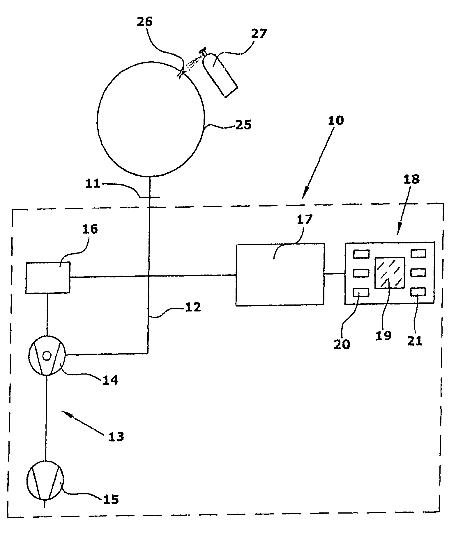
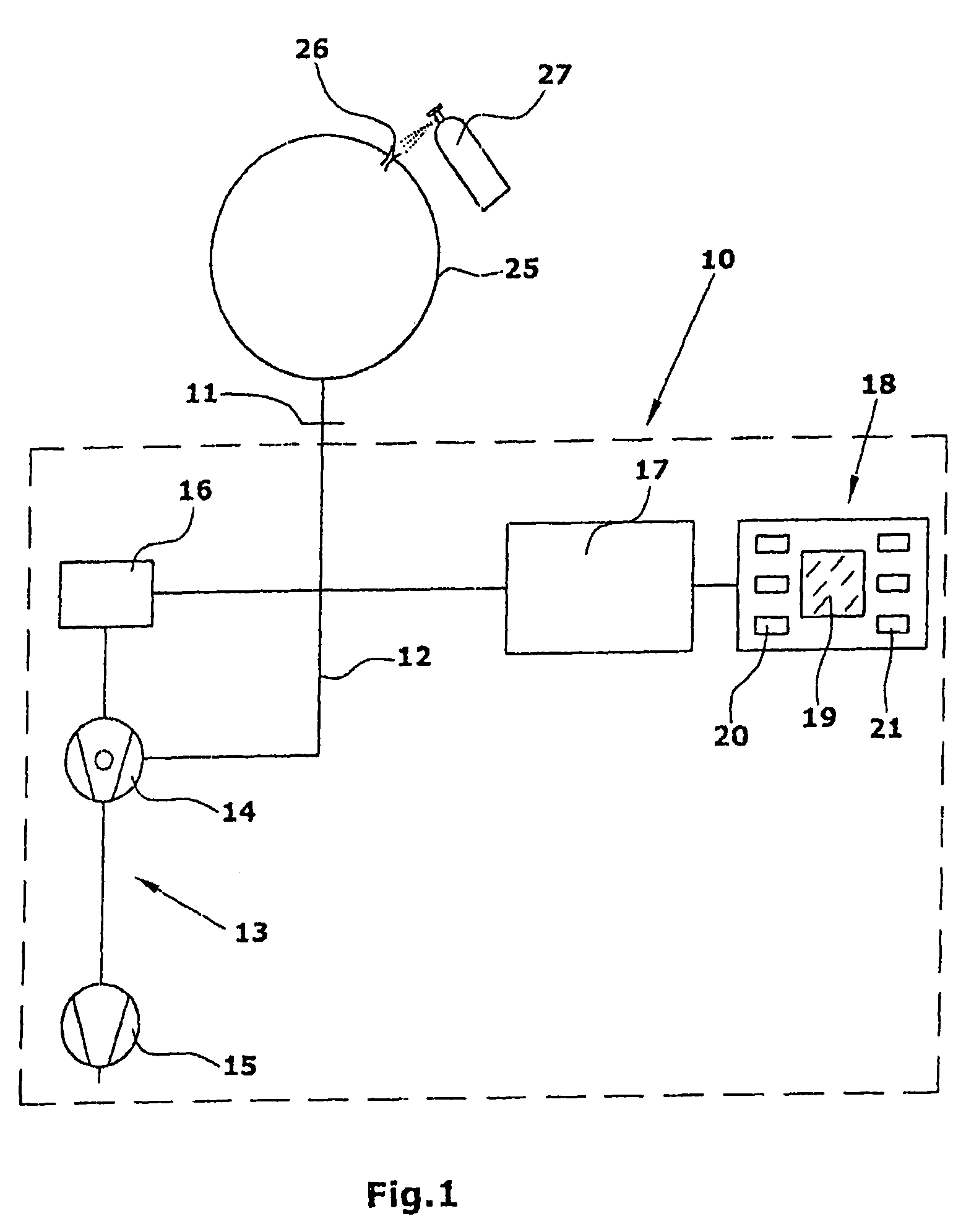
[0018]The leak detector 10 of FIG. 1 comprises an inlet flange 11 to which the container to be tested is connected. A conduit 12 leads from the inlet flange 11 to the vacuum pump device 13. The vacuum pump device 13 is comprised of a turbo molecular pump 14 and a downstream pre-vacuum pump 15. The conduit 12 is connected to a side inlet of the turbo molecular pump 14, the inlet side of which is connected to a mass spectrometer 16. In the turbo molecular pump 14, a test gas, e.g., helium, contained in the drawn-off gas reaches the mass spectrometer 16 in the counter flow to the feed direction, where it is identified. The mass spectrometer 16 supplies the volume signal representing the volume of test gas detected to a microcomputer 17, which executes the treatment described in the following. The microcomputer 17 is connected with a control unit 18 comprising a display device 19, e.g., a monitor, an input device 20 with various keys and a zero key 21.

[0019]The container 25 to be examin...


PUM


Abstract

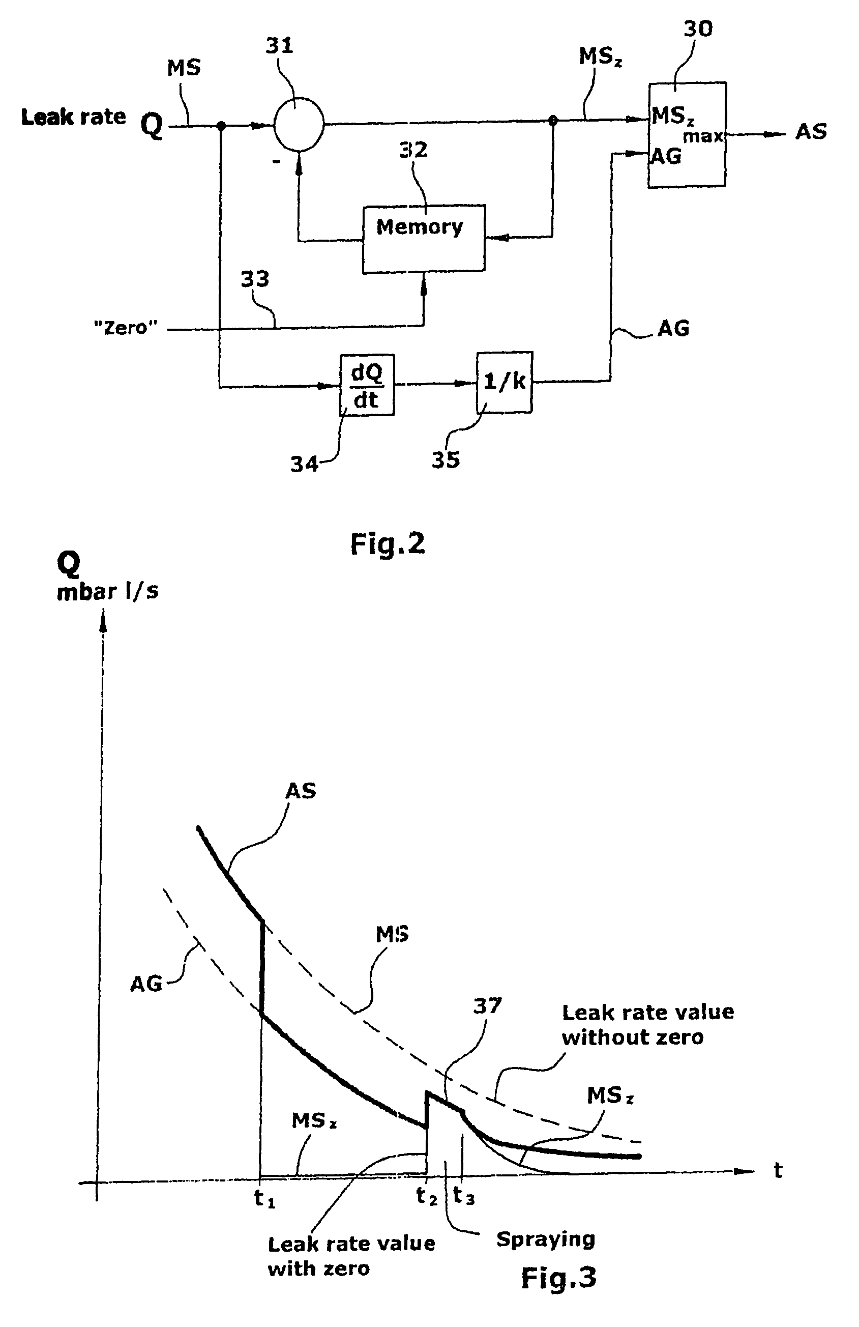
In leak detection, the signal generated by a test gas is superposed by interferences which fade as the vacuum generation in a container proceeds. Depending on the negative slope of the volume signal (MS), a lower indication limit (AG) is calculated. Upon activation of a zero function, the volume signal (MS) is not reduced to zero but only to the level of the indication limit (AG). Any exceeding of the indication limit is identified as a leak. Thus, the maximum sensitivity of the leak detection is guaranteed at any time.

Description

FIELD OF THE INVENTION[0001]The invention refers to a method for leak detection, wherein gas is drawn off and the presence of test gas is detected in the drawn-off gas.BACKGROUND OF THE INVENTION[0002]Minute leak rates of a container can be reliably determined by the vacuum method. The smaller the leak rate, the higher the demands regarding purity and final vacuum. In local leak detection, a vacuum pump evacuates the container until the test pressure required for the leak detector is reached. Suspected leaks are then sprayed with a fine test gas jet from outside. Test gas entering the container is pumped off by the vacuum pump and detected by a mass spectrometer.[0003]A test gas frequently used for leak detectors is helium. There is a problem with the restricted selectivity of the mass spectrometer. Water precipitates both on the outside and on the inside of containers used for leakage measuring. The H2 component of water also includes parts whose presence susceptibly interfere with...

Claims


Application Information

Patent Timeline
Patent Type & Authority Patents(United States)
IPC IPC(8): G01M3/02G01M3/26
CPCG01M3/202
Inventor LIEBICH, JORNROLFF, RANDOLFKILIAN, RALF
Owner INFICON GMBH
Learn More