
Reduced perforation distal tip for an implantable cardiac electrotherapy lead

Inactive Publication Date: 2010-09-21
PACESETTER INC
View PDF35 Cites 41 Cited by
  • Summary
  • Abstract
  • Description
  • Claims
  • Application Information

AI Technical Summary

Problems solved by technology

Cardiac perforation of the right ventricle (“RV”) wall is a risk associated with all transvenous lead implantations to the RV apical site, especially active fixation leads, leads with smaller diameters, and defibrillation leads.
Additionally, a lead that has perforated the myocardium may be non-functioning and may cause chest pain or pneumothorax.

Method used


Image

  • Reduced perforation distal tip for an implantable cardiac electrotherapy lead
  • Reduced perforation distal tip for an implantable cardiac electrotherapy lead
  • Reduced perforation distal tip for an implantable cardiac electrotherapy lead

Examples


Embodiment Construction

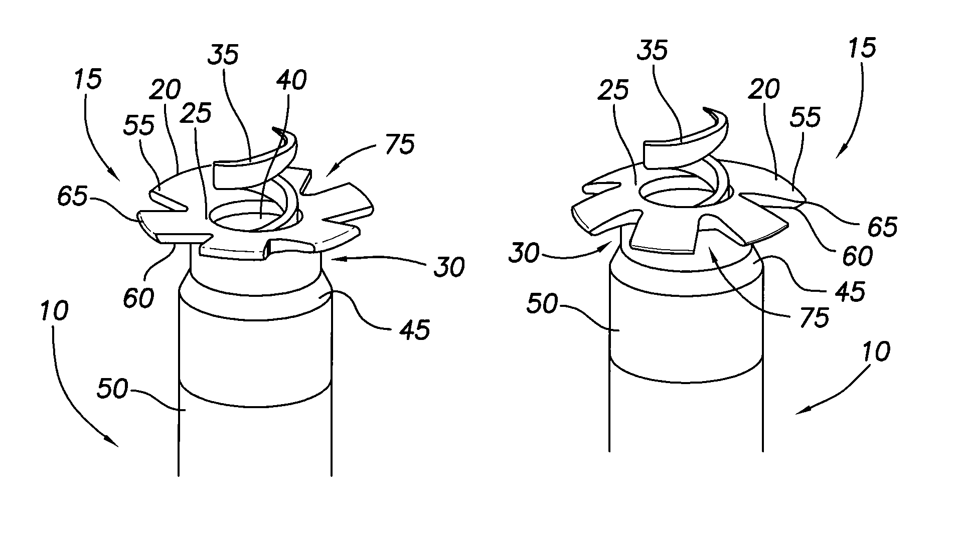
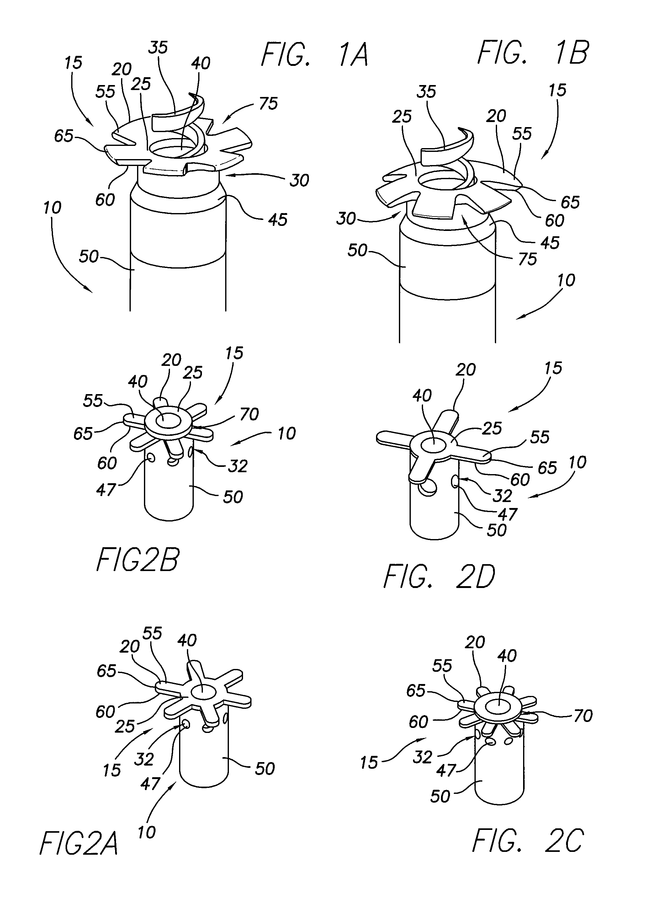
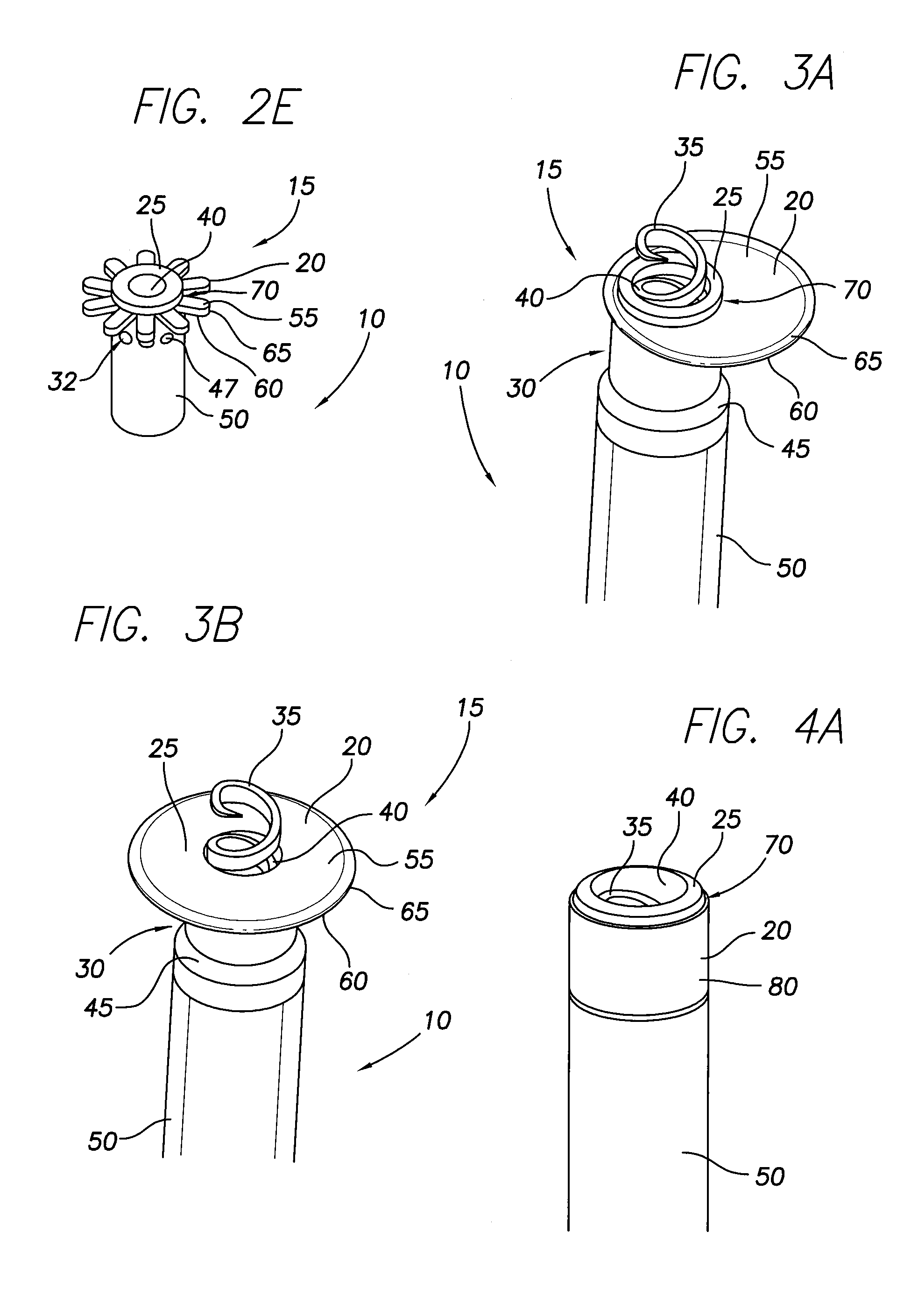
[0045]The present application describes tubular body 10 of an implantable cardiac electrotherapy lead (e.g., a bradycardia lead, tachycardia lead, or etc.). The lead tubular body 10 has a distal end 15 configured to reduce the likelihood of myocardial perforation when the lead distal end 15 contacts a myocardial surface during the implantation of the lead within the heart of a patient. In some embodiments, the lead tubular body 10 includes a distal end 15 that has a modifiable diameter that can be increased as the distal end 15 approaches a myocardial surface. In some embodiments, the lead tubular body 10 includes a distal end 15 that provides a soft material interface for contacting the myocardial surface. In some embodiments, the lead tubular body 10 includes a distal end 15 having resistance features that provide resistance to the distal end 15 penetrating the myocardial surface. In some embodiments, the lead tubular body 10 includes a distal end 15 employing any two or more of t...


PUM


Abstract

An implantable cardiac electrotherapy lead is disclosed herein. In one embodiment, the lead includes a tubular body having a distal end with a first soft resilient member. The member extends or is extendable from the distal end radially outward relative to a longitudinal axis of the tubular body.

Description

FIELD OF THE INVENTION[0001]The present invention relates to medical apparatus and methods. More specifically, the present invention relates to implantable cardiac electrotherapy leads and methods of using such leads.BACKGROUND OF THE INVENTION[0002]Cardiac electrotherapy leads are implanted within various locations of a heart to provide pacing and / or defibrillation electrotherapy. Cardiac perforation of the right ventricle (“RV”) wall is a risk associated with all transvenous lead implantations to the RV apical site, especially active fixation leads, leads with smaller diameters, and defibrillation leads. The likelihood of perforation is a function of the lead and / or stylet configuration and the dexterity of the implanting surgeon.[0003]In rare cases, the distal end of a lead acts as a spear that pierces the RV wall, either during implantation of the lead or in the succeeding months. If a lead perforates the myocardium, acute patient symptoms can include pericardial effusion, cardi...

Claims


Application Information

Patent Timeline
IPC IPC(8): A61N1/00
CPCA61N1/0573A61N1/0575
Inventor FLANNERY, CONORINDRAVUDH, VIROTEDOAN, PHONG D.MUFF, DIANE
Owner PACESETTER INC
Learn More