
Method and device for improving cardiac function

a technology of cardiac function and a device, applied in the field of methods and devices for improving cardiac function, can solve the problems of impaired pumping action of the heart, thickening of the left ventricle's myocardium, and interfering with effective heart contraction

Inactive Publication Date: 2010-09-21
WILK PATENT
View PDF4 Cites 39 Cited by
  • Summary
  • Abstract
  • Description
  • Claims
  • Application Information

AI Technical Summary

Benefits of technology

[0007]It is another object of the present invention to provide a surgical method for treating congestive heart failure which may be used to facilitate minimally invasive procedures.
[0009]A method for improving cardiac performance comprises, in accordance with the present invention, (a) passing a compressive cardiac implant through an anterior intraventricular vein of a patient's heart to a position proximate an apex or lower end of a left ventricle of the patient's heart, (b) subsequently moving a distal end portion of the compressive cardiac implant from the anterior intraventricular vein into the patient's left ventricle, (c) thereafter passing the distal end portion of the compressive cardiac implant through a septum of the patient's heart and into a right ventricle thereof, (d) engaging the distal end portion of the compressive cardiac implant with the septum, and (e) operating the compressive cardiac implant to compress the apex or lower end of the patient's left ventricle so as to reduce the effective volume of the left ventricle.

Problems solved by technology

In either case, the pumping action of the heart is impaired.
In another malfunction, left ventricular hypertrophy, the myocardium of the left ventricle becomes thickened to the point of interfering with effective heart contraction.

Method used


Image

  • Method and device for improving cardiac function
  • Method and device for improving cardiac function
  • Method and device for improving cardiac function

Examples


Embodiment Construction

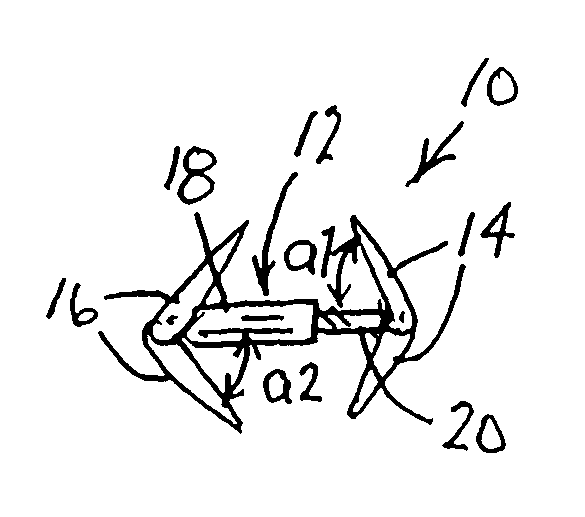
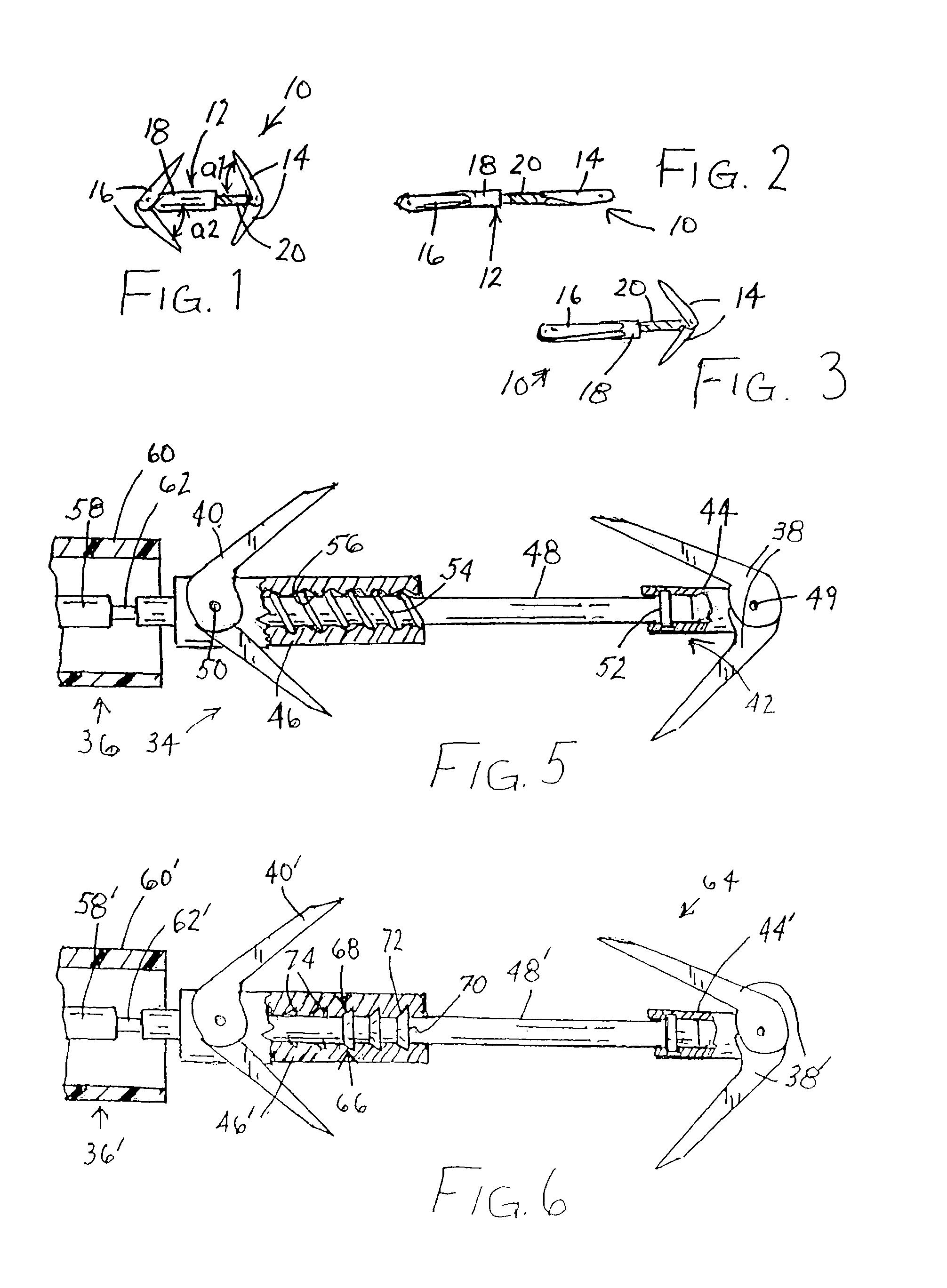
[0026]FIGS. 1-3 illustrate a clamping device 10 for applying compressive force to a lower or apical portion of a patient's heart for purposes of reducing ventricular volume in the treatment of congestive heart failure. Clamping device 10 includes a shaft 12 provided at a first end with a first pair of arms or barbs 14 and at a second end with a second pair of arms or barbs 16. Shaft 12 includes an outer tubular member 18 receiving an inner rod or tubular member 20. Arms 14 are pivotably mounted to inner member 20, while arms 16 are pivotably mounted to outer tubular member 18. Arms 16 and 16 are spring biased to assume an angled opened configuration shown in FIG. 1. In the configuration, arms 14 and 16 are inclined toward each other at acute angles a1 and a2 with respect to shaft 12.

[0027]FIGS. 2 and 4A show clamping device 10 in a fully closed configuration in which the clamping device is disposed inside the distal end of a steerable deployment catheter 22. During a deployment and ...


PUM


Abstract

In a method for improving cardiac performance, a compressive cardiac implant is passed through an anterior intraventricular vein of a patient's heart to a position proximate an apex or lower end of a left ventricle of the patient's heart. A distal end portion of the compressive cardiac implant is moved from the anterior intraventricular vein into the patient's left ventricle and thereafter passed through a septum of the patient's heart and into a right ventricle thereof. The distal end portion of the compressive cardiac implant is then engaged with the septum, and the compressive cardiac implant is operated to compress the apex or lower end of the patient's left ventricle so as to reduce the effective volume of the left ventricle.

Description

CROSS-REFERENCE TO RELATED APPLICATION[0001]This application claims the benefit of U.S. Provisional Patent Application No. 60 / 756,005 filed Jan. 4, 2006.BACKGROUND OF THE INVENTION[0002]This invention relates to a method and device for improving cardiac function, particularly where there is congestive heart failure.[0003]Congestive heart failure occurs, inter alia, where there has been a heart attack or an infection. In either case, the pumping action of the heart is impaired. In another malfunction, left ventricular hypertrophy, the myocardium of the left ventricle becomes thickened to the point of interfering with effective heart contraction.[0004]A surgical procedure for treating congestive heart failure involves inserting cardiac implant into a patient for purposes of constricting or closing off a lower, apical, portion of at least one ventricle of the patient's heart, thereby reducing ventricular volume and enhancing pumping efficiency.[0005]This treatment of congestive heart f...

Claims


Application Information

Patent Timeline
IPC IPC(8): A61B1/00
CPCA61B17/0057A61B2017/00115A61B2017/00243A61B2017/00579A61B2017/00588A61B2017/00632A61B2019/464A61B2090/064
Inventor WILK, PETER J.
Owner WILK PATENT
Learn More