Liquid crystal display device and method of preventing image sticking thereon
a liquid crystal display device and display device technology, applied in the field of preventing image sticking thereon, can solve the problems of poor view angle characteristic of the twisted nematic liquid crystal display device, and achieve the effect of avoiding image sticking
- Summary
- Abstract
- Description
- Claims
- Application Information
AI Technical Summary
Benefits of technology
Problems solved by technology
Method used
Image
Examples
first embodiment
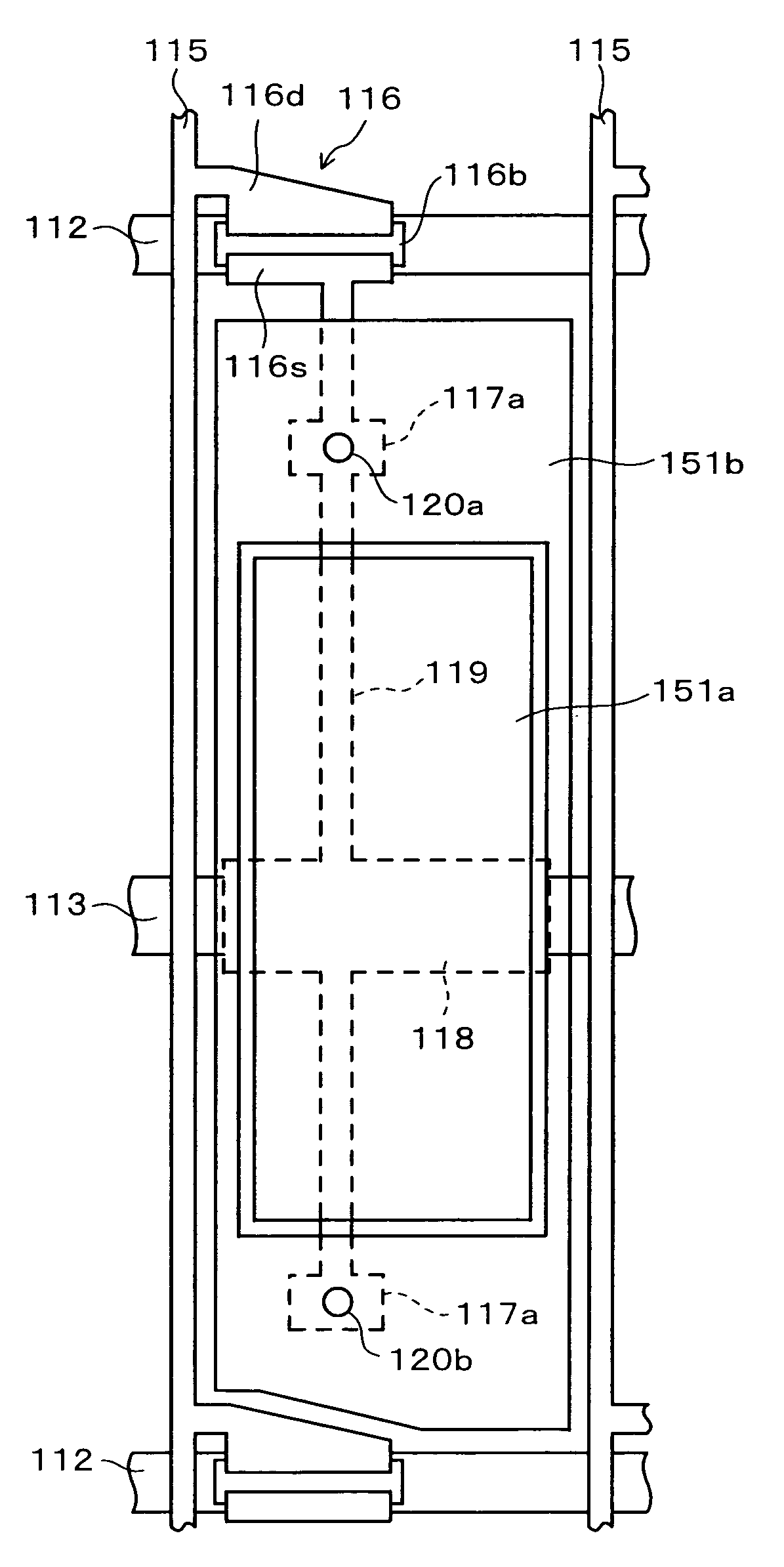
[0121]FIG. 13 is a plan view showing a liquid crystal display device according to a first embodiment of the present invention. Meanwhile, FIG. 14A is a cross-sectional view taken along the VI-VI line in FIG. 13, and FIG. 14B is a cross-sectional view taken along the VII-VII line in FIG. 13.
[0122]On a glass substrate 111 constituting a base of a TFT substrate, there are formed a plurality of gate bus lines 112 extending in a horizontal direction (an X direction) and a plurality of data bus lines 115 extending in a vertical direction (a Y direction). Each rectangular region defined by the gate bus lines 112 and the data bus lines 115 constitutes a picture element region. Meanwhile, on the glass substrate 111, there are formed auxiliary capacitance bus lines 113 disposed parallel to the gate bus lines 112 and intersecting the center of the respective picture element regions.
[0123]A first insulating film 114, which is made of an insulative material such as SiN or SiO2, is formed in a sp...
second modified example
[0137]FIG. 17 is a plan view showing a liquid crystal display device according to a second modified example of the first embodiment, and FIG. 18 is a cross-sectional view taken along the IX-IX line in FIG. 17. In terms of FIG. 17 and FIG. 18, the same constituents as those illustrated in FIG. 15 and FIG. 16 are designated by the same reference numerals, and detailed description thereof will be omitted.
[0138]In the liquid crystal display device of the second modified example shown in FIG. 17 and FIG. 18, shield patterns 138a and 138b which are formed on the same layer as the sub picture element electrode 136a are disposed between the floating sub picture element electrode 136a and the data bus lines 115. These shield patterns 138a and 138b are electrically connected to the auxiliary capacitance bus line 113 through contact holes 137a and 137b, which are formed on the first and second insulating films 114 and 120, respectively. The auxiliary capacitance bus line 113 is maintained eith...
third modified example
[0140]FIG. 19 is a plan view showing a liquid crystal display device according to a third modified example of the first embodiment, and FIG. 20 is a cross-sectional view taken along the X-X line in FIG. 19. In terms of FIG. 19 and FIG. 20, the same constituents as those illustrated in FIG. 15 and FIG. 16 are designated by the same reference numerals, and detailed description thereof will be omitted.
[0141]In the liquid crystal display device of the third modified example shown in FIG. 19 and FIG. 20, the shield patterns 113a and 113b extending from the auxiliary capacitance bus line 113, and shield patterns 142a and 142b formed on the same layer as the sub picture element electrode 136a are disposed between the floating sub picture element electrode 136a and the data bus lines 115. The shield patterns 142a and 142b are electrically connected to the shield patterns 113a and 113b through contact holes 141a and 141b, which are formed on the first and second insulating films 114 and 120,...
PUM
| Property | Measurement | Unit |
|---|---|---|
| dielectric constant | aaaaa | aaaaa |
| dielectric constant | aaaaa | aaaaa |
| electric potential | aaaaa | aaaaa |
Abstract
Description
Claims
Application Information
 - R&D
- Intellectual Property
- Life Sciences
- Materials
- Tech Scout
- Unparalleled Data Quality
- Higher Quality Content
- 60% Fewer Hallucinations
Browse by: Latest US Patents, China's latest patents, Technical Efficacy Thesaurus, Application Domain, Technology Topic, Popular Technical Reports.
© 2025 PatSnap. All rights reserved.Legal|Privacy policy|Modern Slavery Act Transparency Statement|Sitemap|About US| Contact US: help@patsnap.com


