
Formation of a fabric seam by ultrasonic gap welding of a flat woven fabric

a flat woven fabric and fabric seam technology, applied in the direction of instruments, photosensitive materials, other domestic objects, etc., can solve the problems of insufficient resistance of adhesives to machine running conditions, inability to produce the desired seam integrity or uniformity, and the use of adhesives with other reinforcement means such as sewing terminal ends of pmc, tad or engineered fabric, to achieve the effect of enhancing pin seams and inline spiral seams, sufficient strength, and favorable to the formation of fabric seam

Active Publication Date: 2010-09-14
ALBANY INT CORP
View PDF61 Cites 20 Cited by
  • Summary
  • Abstract
  • Description
  • Claims
  • Application Information

AI Technical Summary

Benefits of technology

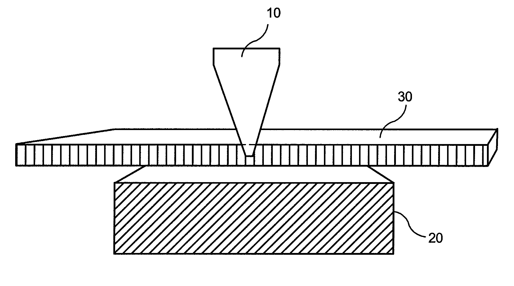
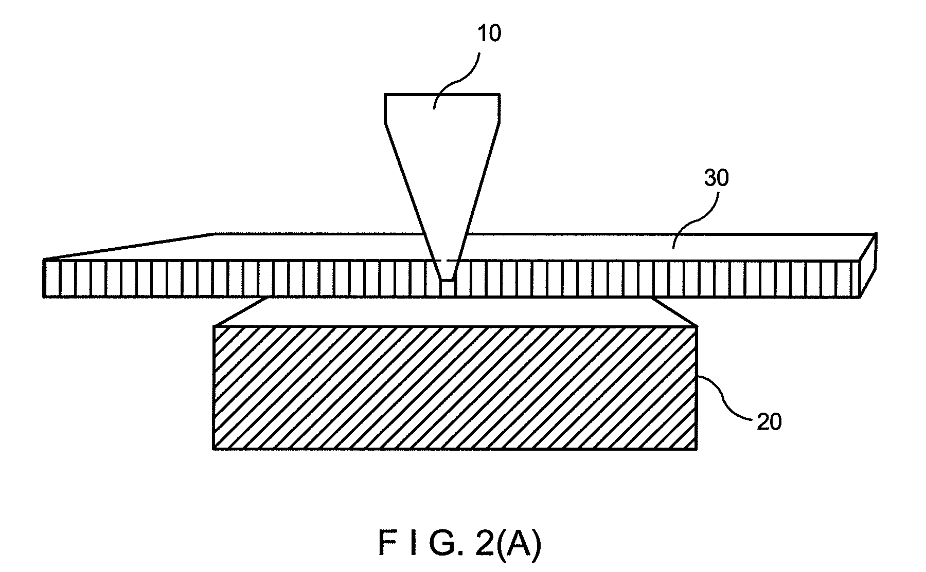
The invention is a method of creating strong and durable seams in flat woven industrial fabrics, such as PMC fabric or TAD fabric, using ultrasonic welding. The method involves setting a distance between a horn and an anvil, placing the material to be welded between the horn and anvil, and welding a portion of that material until a predetermined amount of energy is absorbed. The seam created using this method is stronger and more durable than conventional seams, with a narrower seam area in the MD. The method can also be used to enhance pin seams and inline spiral seams in industrial fabrics. By eliminating the shortcomings of conventional ultrasonic welding, the method achieves smooth fabric seams with sufficient strength and is conducive to the formation of fabric seams by spot welding or along the termination ends of the fabric. The invention also includes a method of minimizing terminal yarn end pullback and seam end termination wear in a fabric.

Problems solved by technology

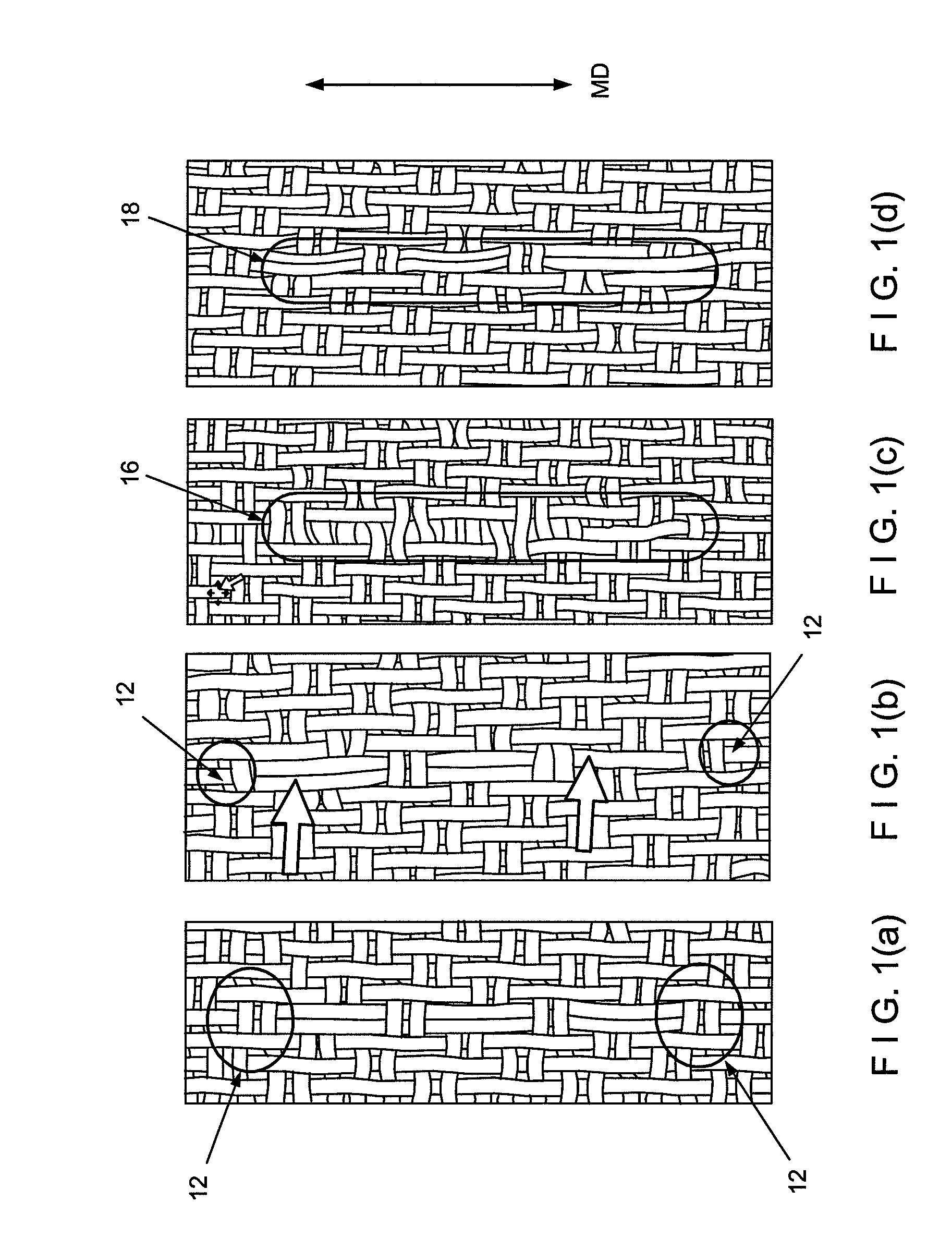
Fabric seam terminations or the ends of the yarns that are interlaced or interwoven to form the seam are susceptible to pulling back when run on a paper, TAD or other industrial machines when the fabric is subjected to machine direction (MD) tension.
However, adhesives are not fully resistant to the machine running conditions, and still allow for pullbacks or yarn slippage to occur over time.
Likewise, the use of adhesives with other reinforcement means such as sewing terminal ends of a PMC, TAD or engineered fabric does not produce the desired seam integrity or uniformity.
Accordingly the overlap region of the seam is typically reinforced by manually gluing 18 (FIG. 1d) to increase its strength; however, gluing is a laborious and time consuming process.
Due to its low precision, it is also hard to limit the glue to only the overlapping yarns.
In addition, the glue eventually either fails due to flexing of the fabric and / or abrasion.
However, unacceptable seam formation results often arise from ultrasonic welding such as excessive melting of the yarns, reduced seam permeability, and distortions in the fabric due to localized shrinkage.
However, this seam is not acceptable for the demands in papermaking as it causes marks in the paper and / or gives uneven drainage.
The risk for paper web breakage is high if such seam is used for a TAD fabric as the tissue web is so thin.
However, this seam is not useful in open structures like TAD fabrics.
While ultrasonic welding has several advantages over conventional seam formation techniques such as sewing or gluing, certain drawbacks of previous ultrasonic welding techniques described above stemmed in part from the fact that conventional ultrasonic welding is based on modifying multiple parameters of time, energy and distance.

Method used


Image

  • Formation of a fabric seam by ultrasonic gap welding of a flat woven fabric
  • Formation of a fabric seam by ultrasonic gap welding of a flat woven fabric
  • Formation of a fabric seam by ultrasonic gap welding of a flat woven fabric

Examples


example

Example 1

[0065]Using a 40 kHz ultrasonic gap welder, a TAD fabric was exposed to a 500 ms weld time and a 1 second hold time (i.e. after welding the horn stays in the welding position for 1 second before raising the horn) with a 40 micrometer amplitude. The gauge pressure on the seam area was 144 kPa and the trigger force (TRS) was 111 N.

[0066]The result of the process is a TAD fabric with strengthened seam yarn terminations (see FIG. 3), which experienced minimal terminal seam yarn pullback during a trial run on a paper machine. In addition, the resulting seam termination ends of the TAD fabric resulted in considerably more strength than seam gluing.

[0067]FIG. 6 compares the breaking strength of a fabric seam for different lengths on the interlocks for both glued and ultrasonically gap welded fabrics with seams. Evidently, the fabrics welded using ultrasonic gap welding of the present invention have higher strength than that of a conventionally glued fabric seam especially when the...


PUM

PropertyMeasurementUnit
widthaaaaaaaaaa
thicknessaaaaaaaaaa
thicknessaaaaaaaaaa

Abstract

The invention relates to ultrasonic gap welding of flat woven fabrics. Specifically, the invention relates to a method of ultrasonic welding the seam termination yarn ends of a fabric using a controlled gap. A mechanical stop may be employed to control the distance or gap between the horn and anvil to a predetermined level based on the depth of welding and amount of weld energy. By adding another degree of control, the ultrasonic gap welding technique of the present invention is able to achieve fabric seams that are stronger than conventional seams, and even those enhanced with gluing, and is conducive to formation of fabric seams by spot welding or along the termination yarn ends of the fabric.

Description

FIELD OF THE INVENTION[0001]The present invention relates to the formation of a fabric seam for a flat woven fabric using a unique ultrasonic welding technique known as ultrasonic gap welding.INCORPORATION BY REFERENCE[0002]All patents, patent applications, documents and / or references referred to herein are incorporated by reference, and may be employed in the practice of the invention.BACKGROUND OF THE INVENTION[0003]During the papermaking process, a cellulosic fibrous web is formed by depositing a fibrous slurry, that is, an aqueous dispersion of cellulose fibers, onto a moving forming fabric in the forming section of a paper machine. A large amount of water is drained from the slurry through the forming fabric, leaving the cellulosic fibrous web on the surface of the forming fabric.[0004]The newly formed cellulosic fibrous web proceeds from the forming section to a press section, which includes a series of press nips. The cellulosic fibrous web passes through the press nips suppo...

Claims


Application Information

Patent Timeline
Patent Type & Authority Patents(United States)
IPC IPC(8): B32B37/00
CPCB29C65/08B29C66/43B29C66/92651B29C66/929D21F1/0054B29C66/1142B29C66/961B29C66/729B29C66/9221B29C66/92613B29C65/00Y10T428/24033B29K2313/00B29L2031/7092Y10T428/192Y10T428/2419B29C66/944B29C66/8322B29C66/9516B29C66/9513B29C66/9517B29C66/73921B29C66/73521B29C66/71B29K2023/12B29K2027/16B29K2067/00B29K2077/00
Inventor LAFOND, JOHN J.BOWDEN, JENNIFER L.KROLL, LYNN F.BOTELHO, JOSEPH
Owner ALBANY INT CORP
Learn More