
Energy supply of a measuring device

a technology for measuring devices and energy supply, which is applied in the direction of emergency protective arrangements for limiting excess voltage/current, emergency protective arrangements for automatic disconnection, instruments, etc., can solve the problems of not always being able to provide a suitable current connection e.g. via cable, voltages which are too high, and special attention to safety is required. , to achieve the effect of convenient attachment and use, and cost-favorabl

Active Publication Date: 2010-09-07
EHNDRESS KHAUZER GMBKH KO KG
View PDF15 Cites 6 Cited by
  • Summary
  • Abstract
  • Description
  • Claims
  • Application Information

AI Technical Summary

Benefits of technology

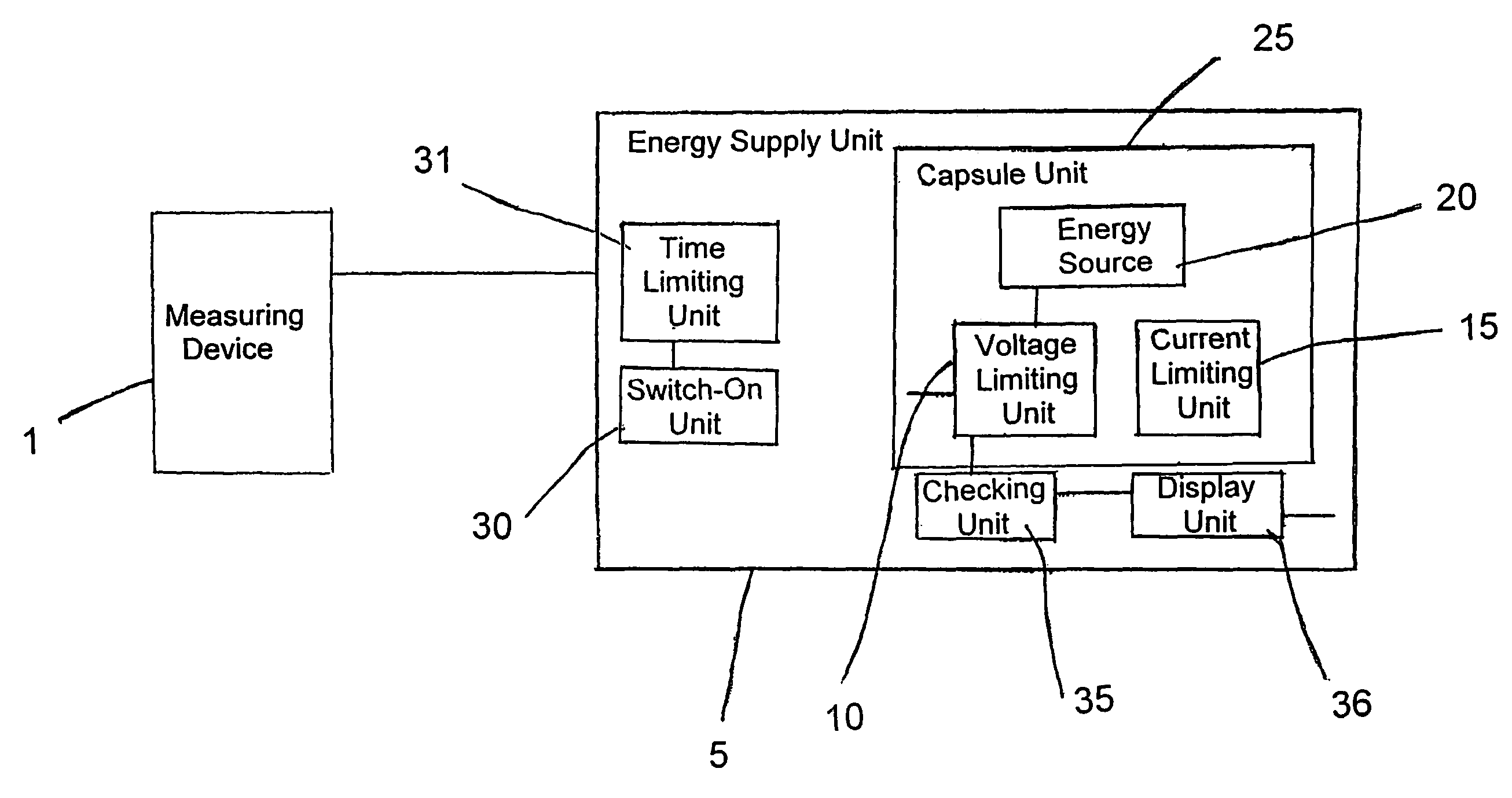
[0007]An embodiment includes that the energy supply unit includes at least one capsule unit, in which the energy source is located. A further development includes that this capsule unit is protected against tampering in a manner such that it can only be opened by the manufacturer and that the energy sources can only be replaced by the manufacturer. An implementation provides that the capsule unit and / or the energy source is destroyed in the case of unauthorized opening. This has the advantage that safety requirements can not be violated by unauthorized (e.g. untrained, or inadvertent) use and that, therefore, possibly highly dangerous situations can be avoided. Thus, it is assured that the part dangerous for explosions, thus the energy source, is only accessible by the manufacturer. On the basis of the capsule unit, the energy source becomes completely a replacement part.
[0008]An advantageous embodiment provides that at least one voltage limiting unit and / or at least one current limiting unit is provided in the capsule unit. In this way, it is possible for the energy source to be replaced even in explosion-endangered areas, since no too high voltages and too high currents or heatings then occur. This is a great advantage, since usually the replacement of a battery means removal of the measuring device from the endangered area or e.g. the emptying of a tank.
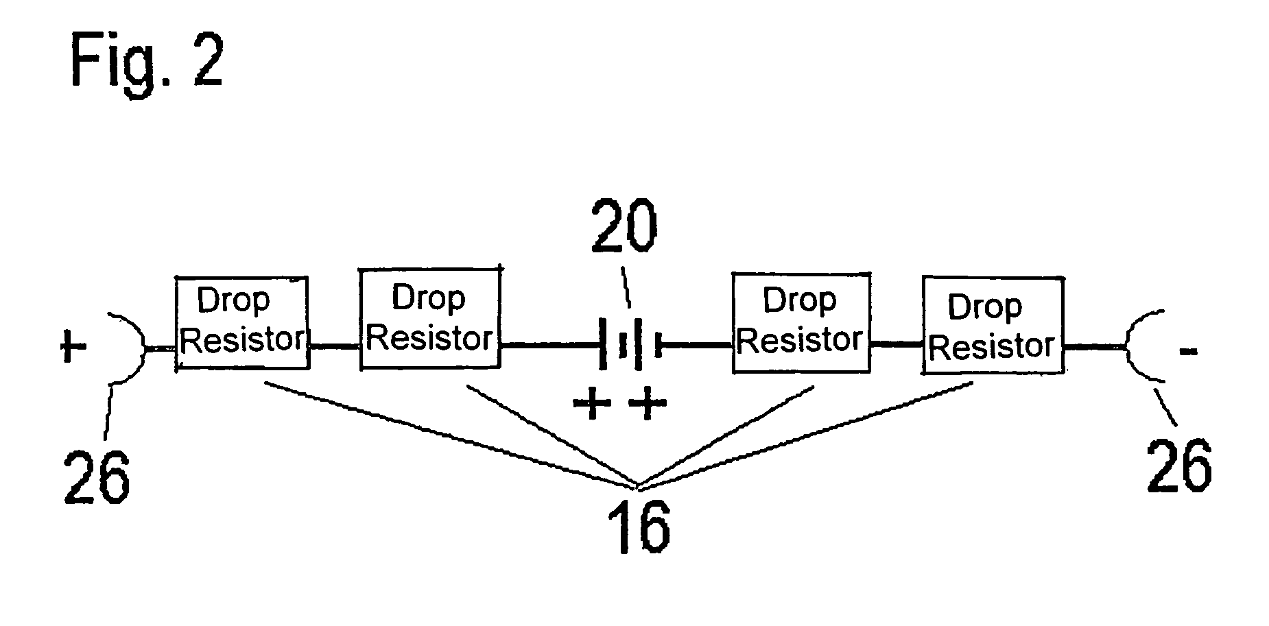
[0009]An advantageous embodiment includes that the voltage limiting unit is at least one drop-resistance. This is a very simple and cost-effective implementation, by way of which an output voltage is reduced in a manner such that no voltage arises, which could lead to an explosion. The size of the resistance depends, in such case, also on the dimensioning of the energy source.
[0010]An advantageous embodiment includes that the current limiting unit is a plurality of drop resistances. In this way, the current, and the associated heating, is spread over a plurality of separate resistances. In this way, a possible explosion because of the heating is likewise prevented. Moreover, these drop resistances represent a very simple and cost-effective solution. Of course, the drop resistances used for the voltage limiting and current limiting can be suitably combined. Also in this case, the dimensioning of resistances depends on the energy source and also on the characteristics of the explosion-endangered area.
[0012]An advantageous embodiment provides that at least one time-limiting unit is provided, which turns the energy supply to the measuring device by the energy supply unit off following an adjustable period of time. This is especially advantageous, because it can happen that the switching-off of the energy supply will be forgotten. The period of time is either determined at the factory or it is adjustable via an appropriate input unit. In this way, also larger time periods can e.g. be specified, when e.g. the filling of a tank is to be observed. Another idea for lowering energy consumption and thus increasing life is to perform a suitable calibration. Thus, most measuring devices transmit their measured values with a 4 . . . 20 mA signal. The absolute current level is of lesser relevance, so that e.g. the upper limit can be reduced, in order to reduce current consumption. This can be accomplished by way of an appropriate calibration.
[0014]An advantageous embodiment provides that the energy supply unit is a modular unit. This permits connecting the energy supply unit with any measuring device for operating such. This can be very cost-favorable. Furthermore, the wide area of application and mobility is also supported by the fact that the operating and attachment is possible in explosion-endangered areas, so that a connecting and the measurement are possible there. For the modular construction, there is then also a connecting unit with sealing devices, which enable a releasable connection. One implementation provides further that the energy supply unit is adaptable using an adapting unit, so that the attachment and use are made easier.

Problems solved by technology

It is, however, not always possible to provide a suitable current connection e.g. via cable.
A typical problem arises e.g. when fill levels of liquids need to be measured in mobile units.
However, if measurements are done in explosion-endangered zones or areas, then special attention to safety is required.
For instance, a short circuit might lead to voltages which are too high, and high currents might lead to excessive heating.
A further problem is usually that energy units such as batteries or fuel cells are not permitted to be replaced in explosion-endangered areas, because, most often, the process of replacement cancels the protection against explosion or makes it no longer secure.

Method used


Image

  • Energy supply of a measuring device
  • Energy supply of a measuring device
  • Energy supply of a measuring device

Examples


Embodiment Construction

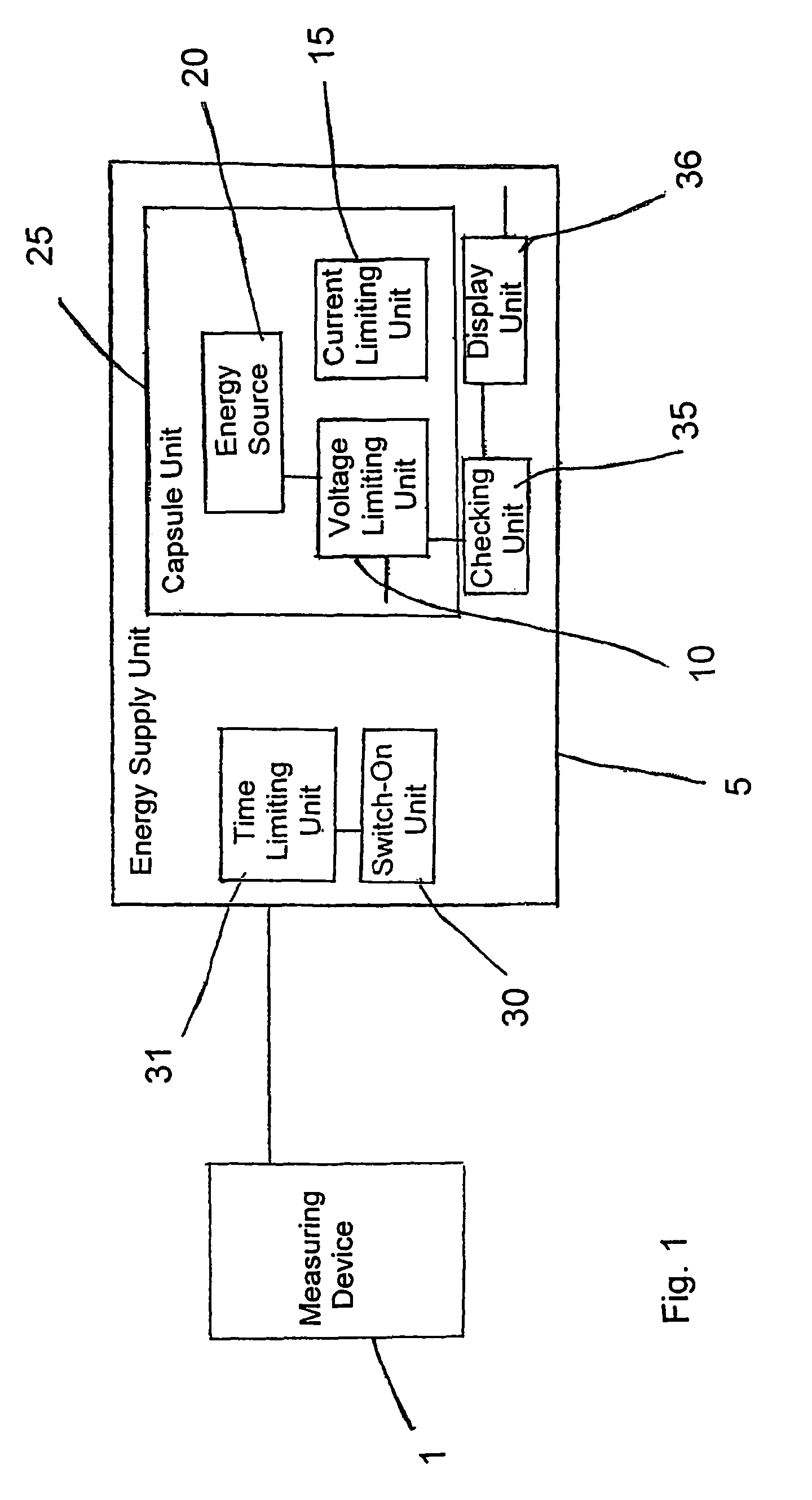
[0020]FIG. 1 shows a block diagram of the measuring device 1 and the energy supply unit 5. The medium to be measured with the measuring device 1 is not shown. Also not shown is that the application, here, is in an explosion endangered area. Present in the energy supply unit 5 is the capsule unit 25. The capsule unit 25 contains the actual energy source 20. In front of source 20 are located a voltage limiting unit 10 and a current limiting unit 15. Both provide the advantage that they enable operation in an explosion-endangered area, and, above all, replacement of the energy source 20, respectively the capsule unit 25, in such an area. The capsule unit 25 is e.g. embodied as a replacement part in such a manner that tampering with it leads to its destruction. Thus, always only the entire capsule unit 25, with energy source 20 and the two limiting units 10, 15, is replaced. This assures, on the one hand, that even during replacement, no explosion can happen, because of the limiting uni...


PUM


Abstract

An energy supply unit for a measuring device for determining and / or monitoring a physical or chemical, process variable of a medium. Included is at least one voltage limiting unit and / or at least one current limiting unit in the energy supply unit, wherein the voltage limiting unit is embodied in such a manner that arising voltages remain under a value, which leads to an explosion in an explosion-endangered area, and wherein the current limiting unit is embodied in such a manner that arising currents and / or heatings associated therewith remain under a value, which leads to an explosion in an explosion-endangered area.

Description

FIELD OF THE INVENTION[0001]The invention relates to an energy, or power, supply unit for a measuring device for determining and / or monitoring a physical or chemical process variable of a medium. Examples of process variables are fill level, viscosity, pressure, density or also the pH-value of a medium. The measuring devices are, in turn, correspondingly equipped to measure the variable of interest. Endress+Hauser manufactures and sells e.g. pressure measuring devices, under the mark Cerabar.BACKGROUND OF THE INVENTION[0002]Measuring devices require an energy supply for the measuring, evaluation and, in appropriate cases, also display of the measured values. It is, however, not always possible to provide a suitable current connection e.g. via cable. A typical problem arises e.g. when fill levels of liquids need to be measured in mobile units. In such cases, it makes sense to use e.g. batteries or fuel cells. However, if measurements are done in explosion-endangered zones or areas, t...

Claims


Application Information

Patent Timeline
Patent Type & Authority Patents(United States)
IPC IPC(8): H02H9/00
CPCH02H9/008
Inventor SCHAEFER, KLAUSTRINLER, JOERGKOPRIAN, ALEXANDER
Owner EHNDRESS KHAUZER GMBKH KO KG
Learn More