Semiconductor device and method of manufacturing the same
a technology of semiconductor devices and semiconductors, applied in semiconductor devices, semiconductor/solid-state device details, electrical apparatus, etc., can solve the problems of low degree of freedom of wiring, large hole size, and large area required, and achieve the effect of increasing the degree of wiring freedom and enhancing functionality
- Summary
- Abstract
- Description
- Claims
- Application Information
AI Technical Summary
Benefits of technology
Problems solved by technology
Method used
Image
Examples
first embodiment
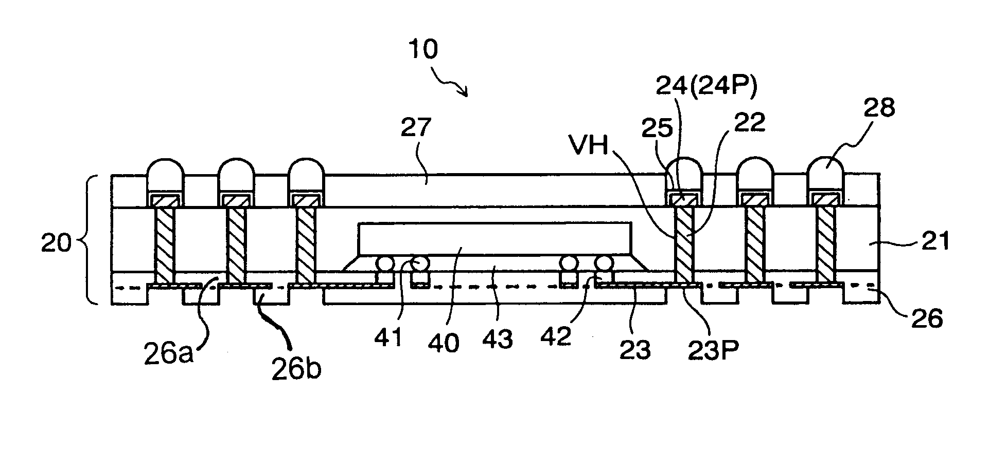
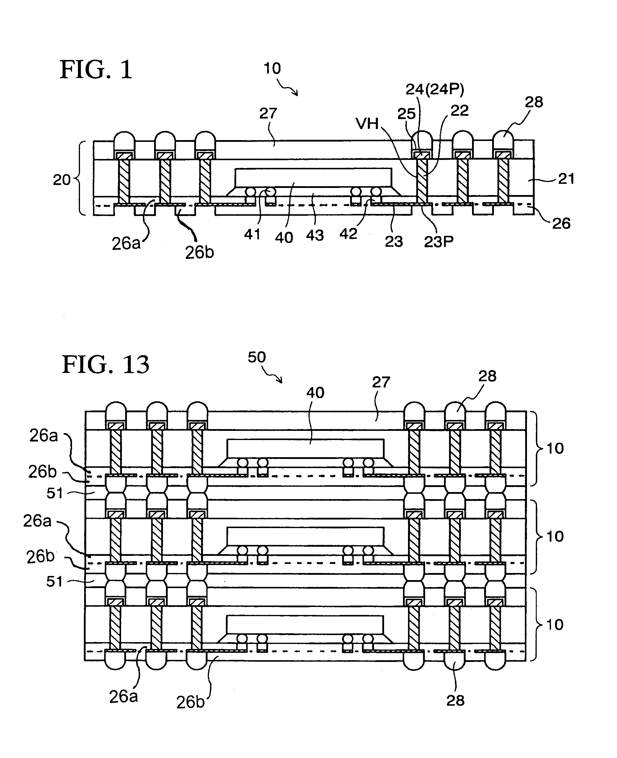
[0036]FIG. 1 schematically shows a cross-sectional structure of a semiconductor device according to the present invention.
[0037]The semiconductor device 10 according to this embodiment includes a wiring board 20 used as a package, and a semiconductor element (silicon (Si) chip) 40 buried in this package (wiring board) 20. In the illustrated example, one semiconductor chip 40 is buried in one package. However, two or more semiconductor chips 40 may be appropriately buried therein depending on functions required for the present device 10.
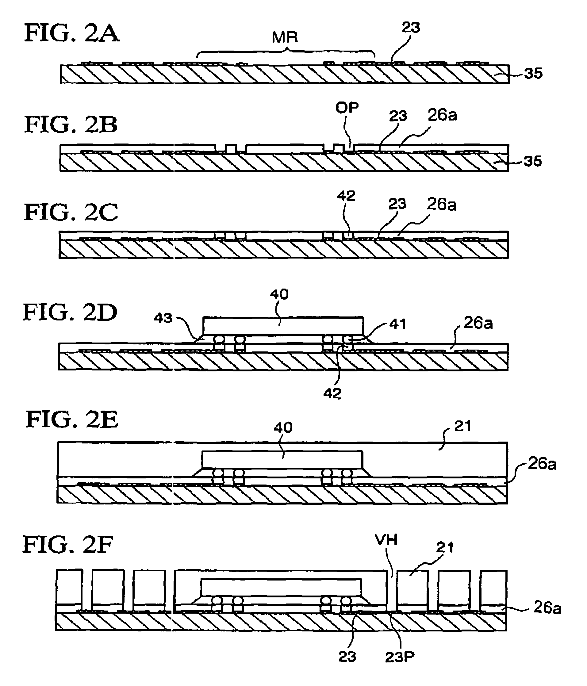
[0038]In the package (wiring board) 20, reference numeral 21 denotes an insulating base material (e.g., a resin layer made of epoxy resin or the like) which serves as a base for the wiring board. In this resin layer 21, via holes VH piercing the resin layer 21 in the thickness direction are formed in a region around the semiconductor chip 40. These via holes VH are filled with conductors 22 (e.g., metal such as copper (Cu)). One end (lower surface in ...
second embodiment
[0061]FIG. 4 schematically shows a cross-sectional structure of a semiconductor device according to the present invention.
[0062]In this embodiment, similar to the first embodiment (FIG. 1), the semiconductor device 10a includes a wiring board 20a used as a package, and the semiconductor chip 40 buried in this package (wiring board) 20a. The package (wiring board) 20a in this embodiment differs from the package (wiring board) 20 in the first embodiment in the following points: a lower protective film 29 has a two-layer structure including an insulating layer Li on an exposed side and a solder resist layer L2 on an internal layer side; and the portions (pad portions 30P) of the conductor layer 30 which correspond to the conductors 22 are exposed, while the conductor layer 30 is electrically connected to the electrode terminals 41 of the chip 40, to one surface (lower surface) of the wiring board 20a via the conductor layer 23. Other components and functions thereof are the same as tho...
third embodiment
[0066]FIG. 7 schematically shows a cross-sectional structure of a semiconductor device according to the present invention.
[0067]In this embodiment, similar to the second embodiment (FIG. 4), the semiconductor device 10b includes a wiring board 20b used as a package, and the semiconductor chip 40 buried in this package (wiring board) 20b. The package (wiring board) 20b in this embodiment differs from the package (wiring board) 20a in the second embodiment in the following points: heat spreading via holes (thermal vias) TH are formed in the resin layer 21 to communicate with the surface of the semiconductor chip 40 which is opposite to the surface having the electrode terminals 41 formed thereon; and the thermal vias TH are filled with the conductors 22 as thermally conductive bodies, and furthermore, the pad portions 24P (Ni / Au layer 25) on the conductors 22 are exposed from the solder resist layer 27 or covered with the exposed solder bumps 31 as thermally conductive bodies. Other c...
PUM
 Abstract
Description
Claims
Application Information
 - R&D
- Intellectual Property
- Life Sciences
- Materials
- Tech Scout
- Unparalleled Data Quality
- Higher Quality Content
- 60% Fewer Hallucinations
Browse by: Latest US Patents, China's latest patents, Technical Efficacy Thesaurus, Application Domain, Technology Topic, Popular Technical Reports.
© 2025 PatSnap. All rights reserved.Legal|Privacy policy|Modern Slavery Act Transparency Statement|Sitemap|About US| Contact US: help@patsnap.com


