Rear projection display and circuit and method for adjusting image thereof

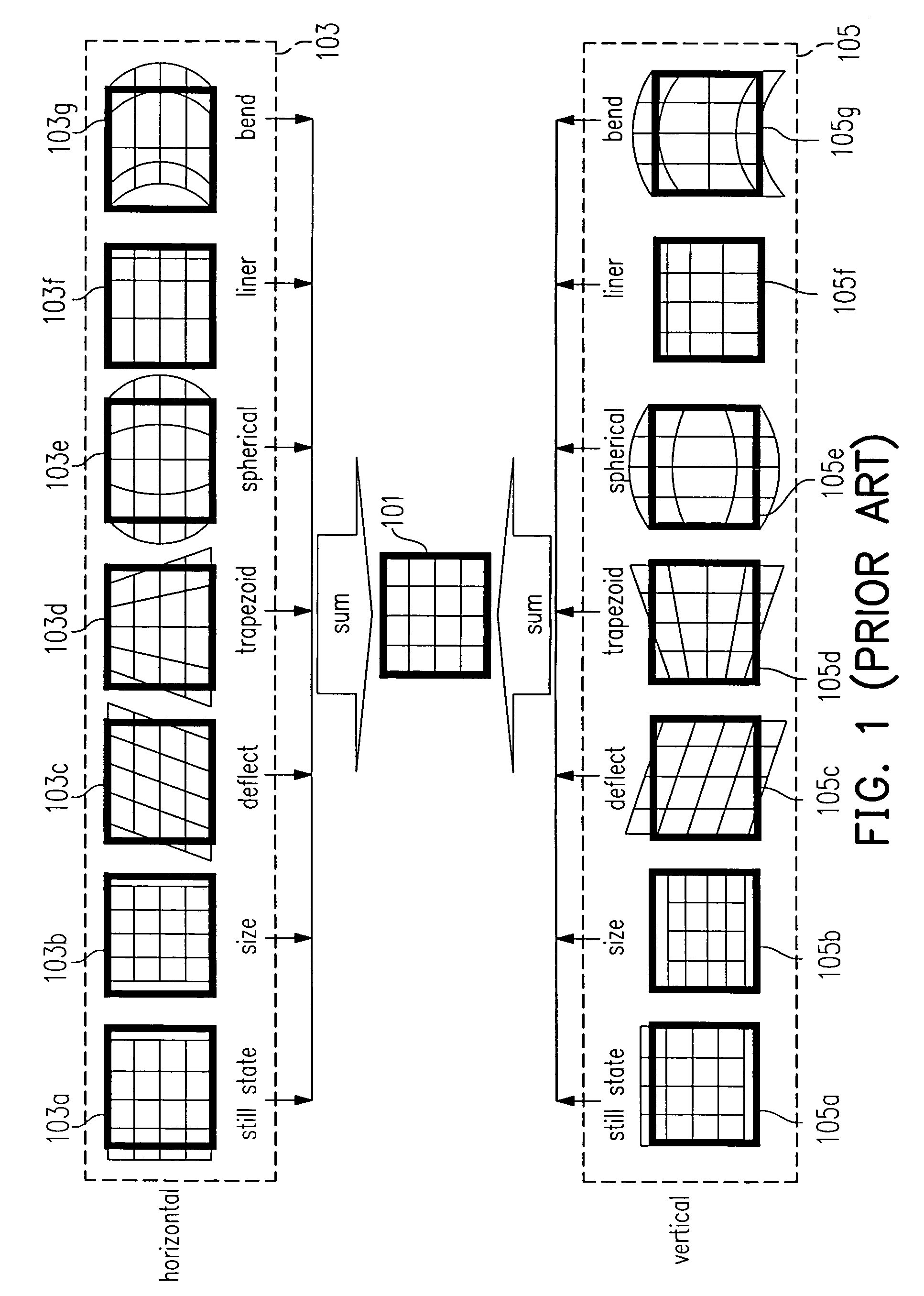
a technology of rear projection display and circuit, applied in the direction of pulse technique, color signal processing circuit, instruments, etc., can solve the problems of not all images displayed in the display b>101/b> are perfect, display may generate specific image distortion patterns different from the conventional technology, and the distortion caused by non-vertical projection can be adjusted

Inactive Publication Date: 2010-08-31
CHUNGHWA PICTURE TUBES LTD
View PDF9 Cites 1 Cited by
  • Summary
  • Abstract
  • Description
  • Claims
  • Application Information

AI Technical Summary

Benefits of technology

[0018]The present invention provides a circuit and a method for adjusting images for amending each pixel of the distorted image data of the input image data and transmitting the amended image data to the display panel for displaying, thereby solving the problem of the image distortion of higher-order curves existing in the conventional technology, and further recovering the original image on the display completely.

Problems solved by technology

However, not all images displayed in the display 101 are perfect, because the images may be bent, distorted, and so on.
However, for the present developed ultra-thin projection displays, in view of the manufacturing of the relative elements and the manufacturing cost, the display may generate specific patterns of image distortions different from the conventional technology.
Therefore, when a user uses the adjustment apparatus provided by the conventional technology, though an image projected to a non-vertical surface can be adjusted to have a fine adjustment effect, only the distortion caused by non-vertical projection can be adjusted, while the image distortions caused by higher-order curves cannot be adjusted.

Method used


Image

  • Rear projection display and circuit and method for adjusting image thereof
  • Rear projection display and circuit and method for adjusting image thereof
  • Rear projection display and circuit and method for adjusting image thereof

Examples


Embodiment Construction

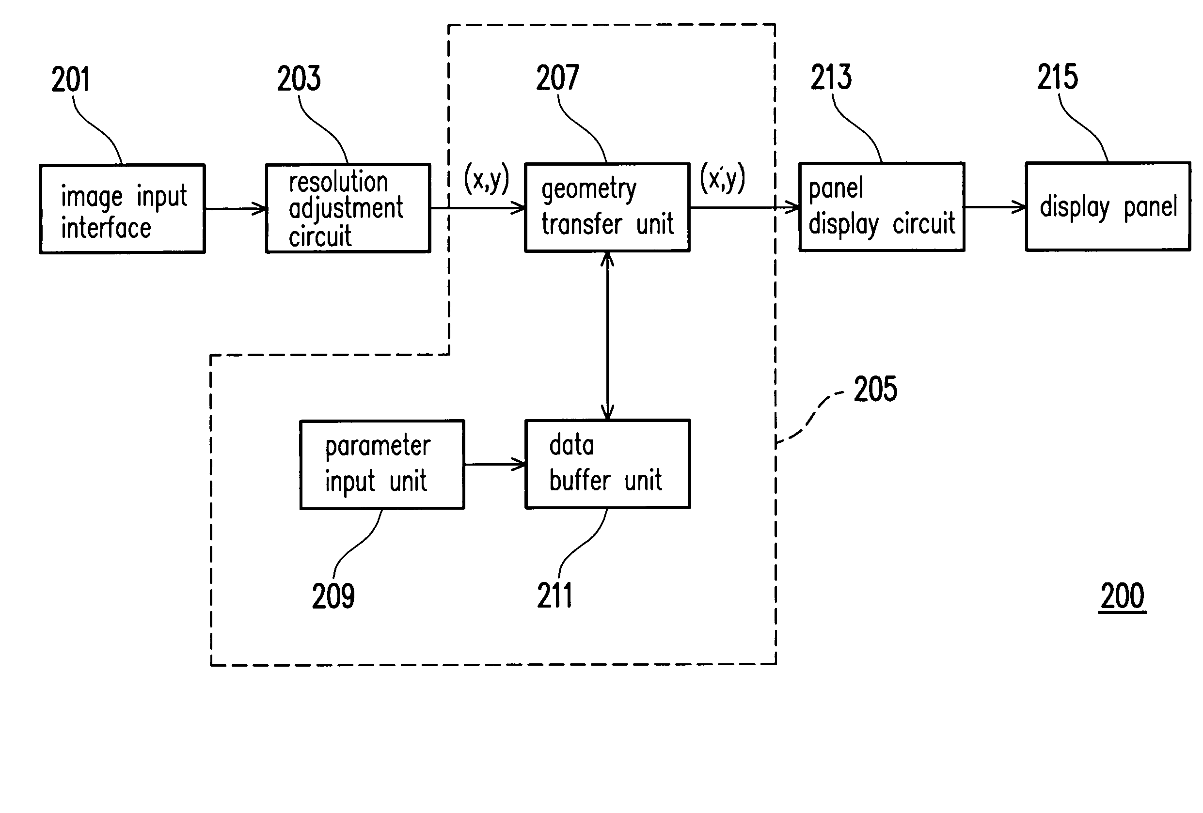
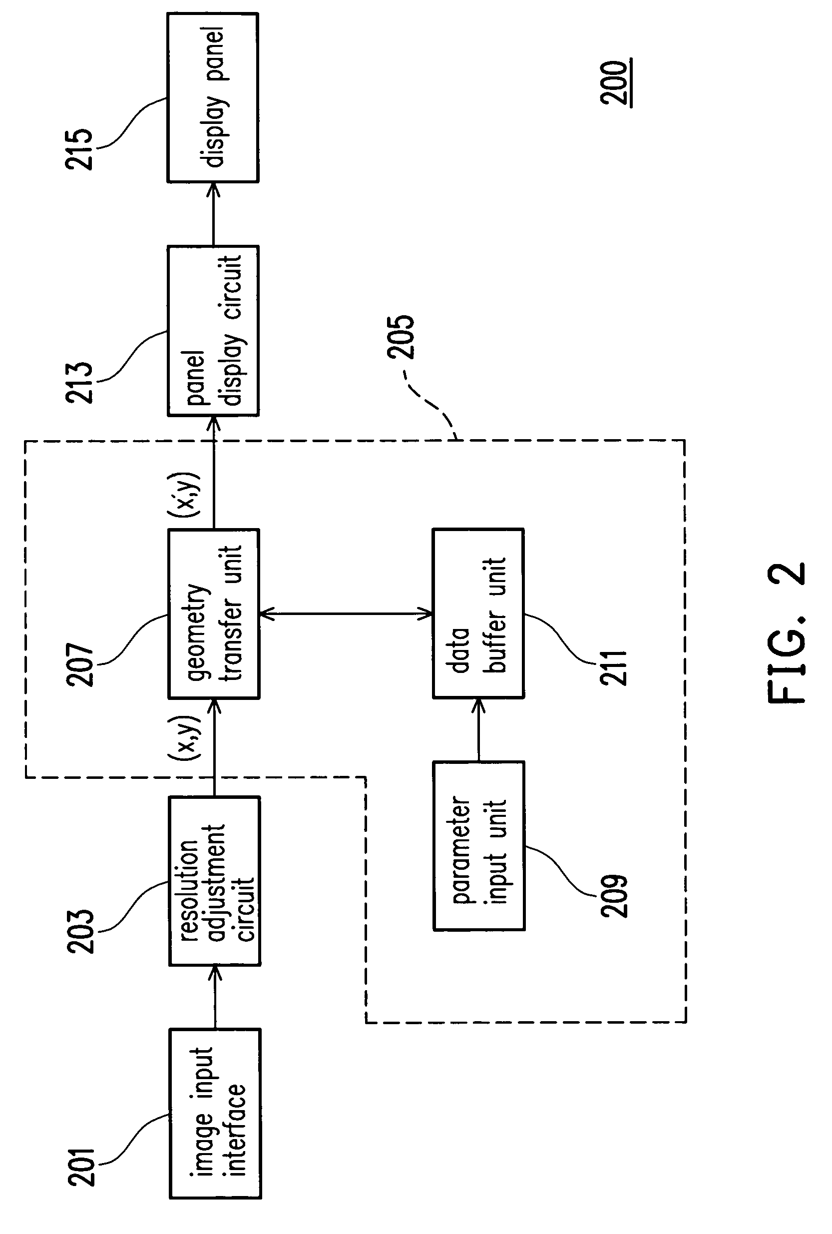
[0026]The projection display technology of a projection display is an indirect imaging technology, using a set of lenses, i.e., projection lenses to project images on a screen far away, thereby forming the picture that can be sensed by eyes after an image is generated through the imaging technologies, such as cathode ray tube (CRT) displays, liquid crystal displays (LCDs), or digital light processing (DLP) displays. Projection displays are generally classified into front projection displays and rear projection displays, which are mainly different in the direction from which people can view images on the screen. For a front projection display, people may view images in front of the screen. On the contrary, for a rear projection display, people may view images in rear of the screen, wherein a rear projection television is the most common rear projection application.

[0027]Compared with the conventional front projection display, the rear projection display is a new imaging technology an...


PUM


Abstract

A circuit for adjusting image is adapted for rear projection display. The circuit for adjusting image includes a parameter input unit, a data buffer unit, and a geometry transfer unit. The parameter input unit is used to provide a vertical and a horizontal axis amendment parameters. The data buffer unit couples the parameter input unit to buffer the vertical axis amendment parameter and the horizontal axis amendment parameter. The geometry transfer unit is used to receive input frame data with a plurality of pixels, and then every pixel's vertical axis coordinates multiply the vertical axis amendment parameter to transfer every pixel to a new vertical axis coordinate, and every pixel's horizontal axis coordinates multiply the horizontal axis amendment parameter to transfer every pixel to a new horizontal axis coordinate. Finally, the transferred new vertical and horizontal axis coordinates are transmitted to a display for displaying images for users to watch.

Description

BACKGROUND OF THE INVENTION[0001]1. Field of Invention[0002]The present invention relates to an apparatus and a method for adjusting an image. More particularly, the present invention relates to an apparatus and a method for adjusting an image for a projection display.[0003]2. Description of Related Art[0004]With the great improvement of computer performance and the high development of the Internet and multimedia technology, at present, image information is mostly transferred by means of digital transmission instead of analog transmission. In order to fit the style of modern life, the volumes of video or image apparatuses are gradually becoming light and thin. Conventional cathode ray tube (CRT) displays have the shortcomings of being bulky, occupying more space, and being harmful to the eyes due to radiant rays when outputting images, though they are cheap.[0005]Therefore, recently developed flat panel displays (FPDs), such as liquid crystal displays (LCDs), organic light-emitting ...

Claims


Application Information

Patent Timeline
Patent Type & Authority Patents(United States)
IPC IPC(8): H04N3/22H04N9/74
CPCG09G3/002G09G2320/0233G09G2320/04G09G2320/0693G09G2340/0414G09G2340/0421G09G2340/0471G09G2340/0478G09G2340/14
Inventor TAI, WEN-CHIHCHIOU, SHIAN-JUNLIU, CHIA-LINMO, CHI-NENG
Owner CHUNGHWA PICTURE TUBES LTD
Why Eureka
Try Eureka