Skewed nodal-fibril ePTFE structure

a nodal fibrillary and eptfe technology, applied in the field of structures, can solve the problems of kinking of the tubular structure of the eptfe, the tendency of the eptfe to kink when subjected to bending force, and the risk to the patient, so as to enhance the utility of the eptfe and increase the flexibility and resistance to kinking of the eptfe. the effect of the tubular structur

Inactive Publication Date: 2010-08-31
LIFESHIELD SCI
View PDF19 Cites 0 Cited by
  • Summary
  • Abstract
  • Description
  • Claims
  • Application Information

AI Technical Summary

Benefits of technology

[0010]The ePTFE structure provides an ePTFE tubular structure which has increased flexibility and an increased range of bending of the tubular structure without kinking thereof. The increased flexibility reduces the likelihood of the ePTFE structure becoming kinked during the passage thereof through the more torturous regions of the anatomy of a patient. The increased flexibility and resistance to kinking are provided without having to add support structures, such as coils or rings, to the ePTFE tubular structure. Further, these benefits are achieved without having to increase the outer diameter of the tubular structure. Accordingly, these characteristics of the ePTFE structure which affect the handling and implantation thereof in the body of a patient are preserved while increasing the flexibility and resistance to kinking of the ePTFE structure.
[0012]The method provides a specific orientation of the fibrils which results in the increased flexibility and resistance to kinking of the ePTFE tubular structure. Further, the method is not unduly complex which significantly enhances the utility thereof.

Problems solved by technology

One disadvantage of current thin-walled or thicker-walled implantable ePTFE tubes is their tendency to kink when subjected to bending forces or concentrated external radial forces.
Such kinking is normally undesirable and poses a risk to the patient.
As a result, endoluminal implantation of the graft can be more difficult, such as, for example, when tunneling through tissue is required to implant the graft.
Another disadvantage of grafts having added support structures is that they are often made from materials which are different from the material of the graft wall and require added processing steps such as heat bonding or additional materials such as adhesive to adhere the support structure to the graft.
Differential shrinkage or expansion of the external support structure relative to the ePTFE tube can cause the bond to weaken and / or the graft to twist significantly.
Separation of the support structure from the graft is obviously undesirable.
Such distortion may result in the normally longitudinally linear guideline becoming helical or some other non-linear shape prior to implantation of the vascular graft in the patient, thereby defeating the purpose of the guideline.

Method used


Image

  • Skewed nodal-fibril ePTFE structure
  • Skewed nodal-fibril ePTFE structure
  • Skewed nodal-fibril ePTFE structure

Examples


Embodiment Construction

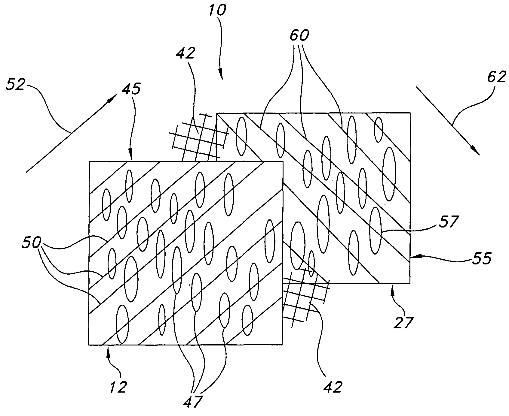
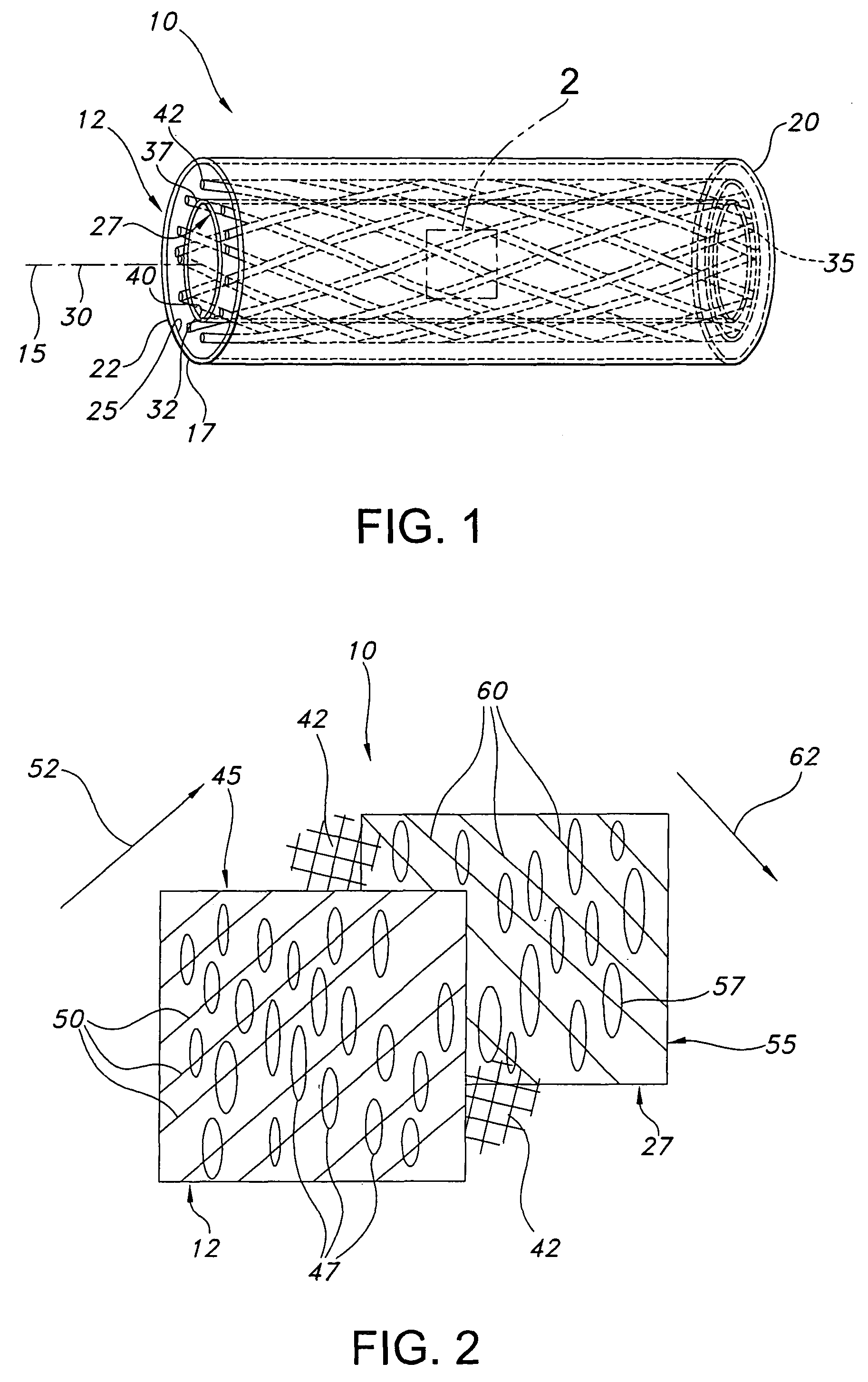
[0021]Referring to the drawings and more particularly to FIG. 1, a skewed nodal-fibril ePTFE structure 10 is shown for implantation within a body. The ePTFE structure 10 includes a cover ePTFE tubular structure 12 which has a longitudinal axis 15, and opposite ends 17, 20. The cover ePTFE tubular structure 12 has outer and inner surfaces 22, 25 and an annular or ring shaped cross-section. The ePTFE structure 10 further includes a liner ePTFE tubular structure 27 which has a longitudinal axis 30, and ends 32, 35. The liner ePTFE tubular structure 27 has outer and inner surfaces, 37, 40, and an annular or ring shaped cross-section.

[0022]The liner ePTFE tubular structure 27 is within the cover ePTFE tubular structure 12 in coaxial relation therewith such that the longitudinal axes 15, 30 coincide with one another. The longitudinal relation between the cover and the liner ePTFE tubular structures 12, 27 provide for the ends 17, 32 to have the same longitudinal positions and for the ends...


PUM

PropertyMeasurementUnit
rotation 82aaaaaaaaaa
rotation 97aaaaaaaaaa
micro-structureaaaaaaaaaa

Abstract

The ePTFE structure includes an ePTFE tubular structure having opposite ends and a longitudinal axis. The ePTFE tubular structure is formed from rotating the opposite ends relative to one another in a direction of rotation about the longitudinal axis. The ePTFE tubular structure has a node and fibril micro-structure in which substantially all of the fibrils are oriented in the direction of rotation.

Description

FIELD OF THE INVENTION[0001]The present invention relates generally to structures containing expanded polytetrafluoroethylene (ePTFE) and methods for making the same. More specifically, the present invention relates to ePTFE tubular structures having a node and fibril micro-structure in which the fibrils have a specific orientation and methods for making such ePTFE tubular structures.BACKGROUND OF THE INVENTION[0002]It is well known to use extruded tubes of ePTFE as implantable intraluminal prostheses, particularly as grafts for vascular, esophageal, ureteral and enteral applications. ePTFE is particularly suitable as an implantable prosthesis as it exhibits superior biocompatibility. ePTFE tubes may be used as vascular grafts in the replacement or repair of a blood vessel as ePTFE exhibits low thrombogenicity. In vascular applications, the grafts are manufactured from ePTFE tubes which have a microporous micro-structure. This micro-structure allows natural tissue ingrowth and cell ...

Claims


Application Information

Patent Timeline
Patent Type & Authority Patents(United States)
IPC IPC(8): A61F2/06A61B19/00D01D5/24B32B27/08B29C47/00B65D39/00B31B45/00B60R21/16D21H11/00F16L11/04B65D1/02
CPCA61F2/07B32B1/08B32B27/12B32B27/322Y10T428/139B29C53/14B29C55/24B29C55/26B29K2027/18B29L2023/007B29L2031/7534A61F2/90A61F2220/0075Y10S623/901B32B2597/00Y10T428/1376Y10T428/13Y10T428/1397Y10T428/1393Y10T428/1352Y10T428/1362A61F2002/072Y10T428/249964
Inventor DURAN, JULIOSOWINSKI, KRZYSZTOFHENDERSON, JAMIE S.
Owner LIFESHIELD SCI
Why Eureka
Try Eureka