
Data storage device using magnetic domain wall movement and method of operating the data storage device

a data storage device and magnetic domain wall technology, applied in the field of data storage device and a method of operating the data storage device, can solve the problems of domain wall deterioration, decrease in the read and write speed of data, increase in power consumption, etc., to improve the effective storage capacity, power consumption, operation speed, and life span.

Inactive Publication Date: 2010-08-24
SAMSUNG ELECTRONICS CO LTD
View PDF11 Cites 4 Cited by
  • Summary
  • Abstract
  • Description
  • Claims
  • Application Information

AI Technical Summary

Benefits of technology

This design enhances effective storage capacity, reduces power consumption, increases operational speed, extends device lifespan, and simplifies manufacturing, while maintaining high recording density and capacity.

Problems solved by technology

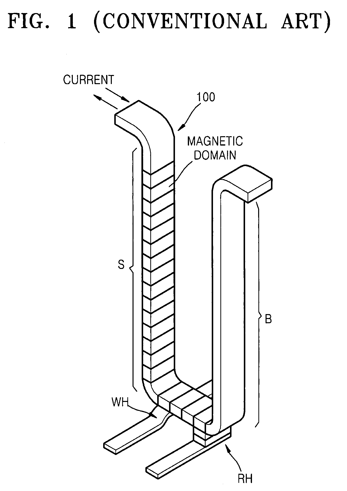
First, since the conventional storage device, which performs the read / write operation by pushing and pulling the magnetic domain walls, requires the buffer area B to be as large as the storage area S, an effective storage capacity is only ½ of a physical storage capacity.
Second, when a read operation is performed by pushing the magnetic domain walls toward the buffer area B, for a next read operation, the magnetic domains of the buffer area B are pulled back toward the storage area S to return the position of the magnetic domains to their original state. Accordingly, power consumption increases and the read and write speed of data decreases.
Third, since the operation of pushing and pulling the magnetic domain walls is repeated, the characteristic of the magnetic domain wall is deteriorated and the life span of the storage device is shortened.
Fourth, since the U-shaped magnetic layer 100 is difficult to manufacture using present etching techniques, it is difficult to produce the conventional storage device. Furthermore, a plurality of notches need to be formed at regular intervals on the surface of the magnetic layer 100 to secure the stability of the magnetic domain wall movement. However, it is very difficult to uniformly form the fine notches on the U-shaped magnetic layer 100.
Therefore, the problems of the conventional storage device stem from the pushing and pulling of the magnetic domain walls and the U shape of the magnetic layer 100.

Method used


Image

  • Data storage device using magnetic domain wall movement and method of operating the data storage device
  • Data storage device using magnetic domain wall movement and method of operating the data storage device
  • Data storage device using magnetic domain wall movement and method of operating the data storage device

Examples


Embodiment Construction

[0046]The present invention will now be described more fully with reference to the accompanying drawings, in which exemplary embodiments of the invention are shown. The thicknesses of the layers and regions illustrated in the drawings are exaggerated for clarity.

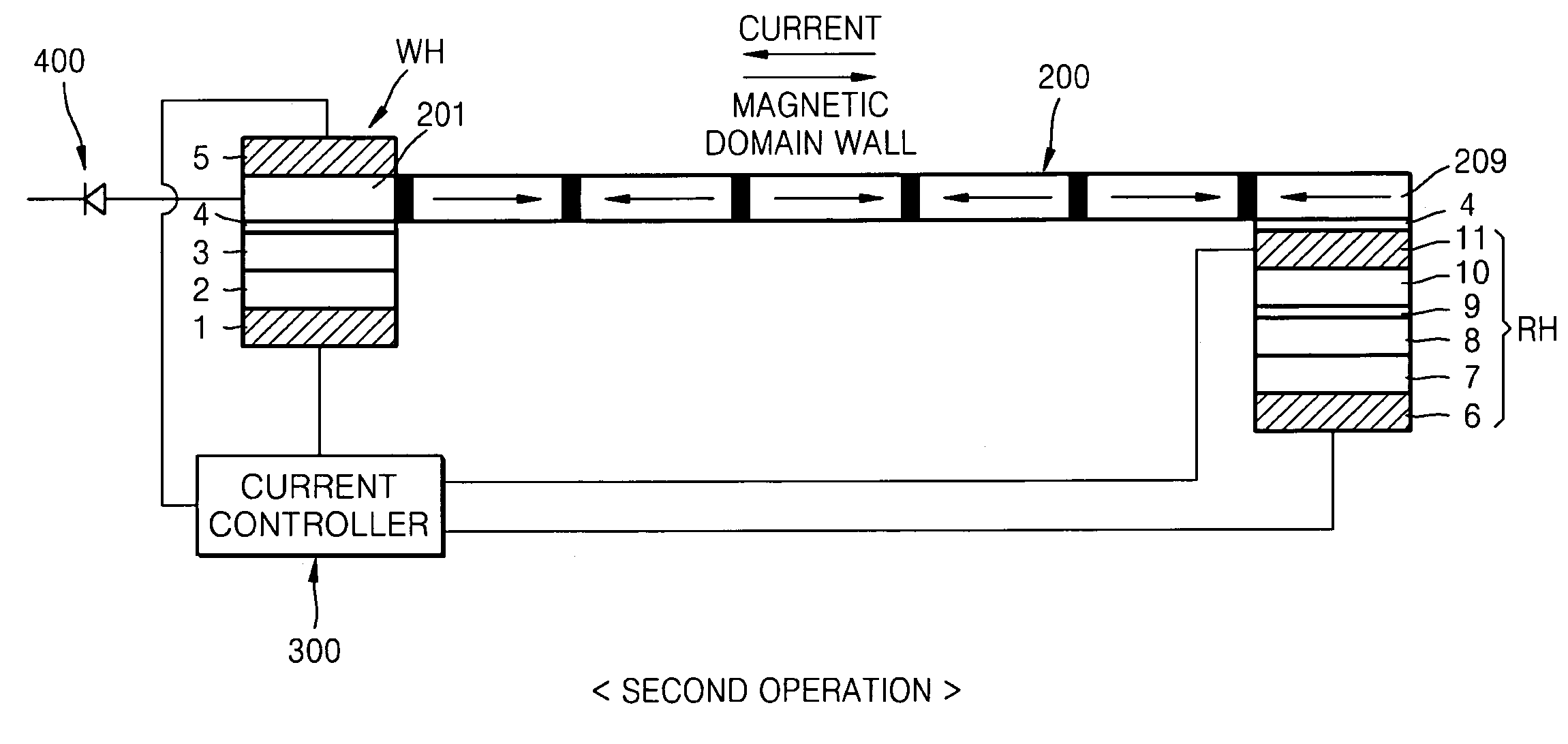
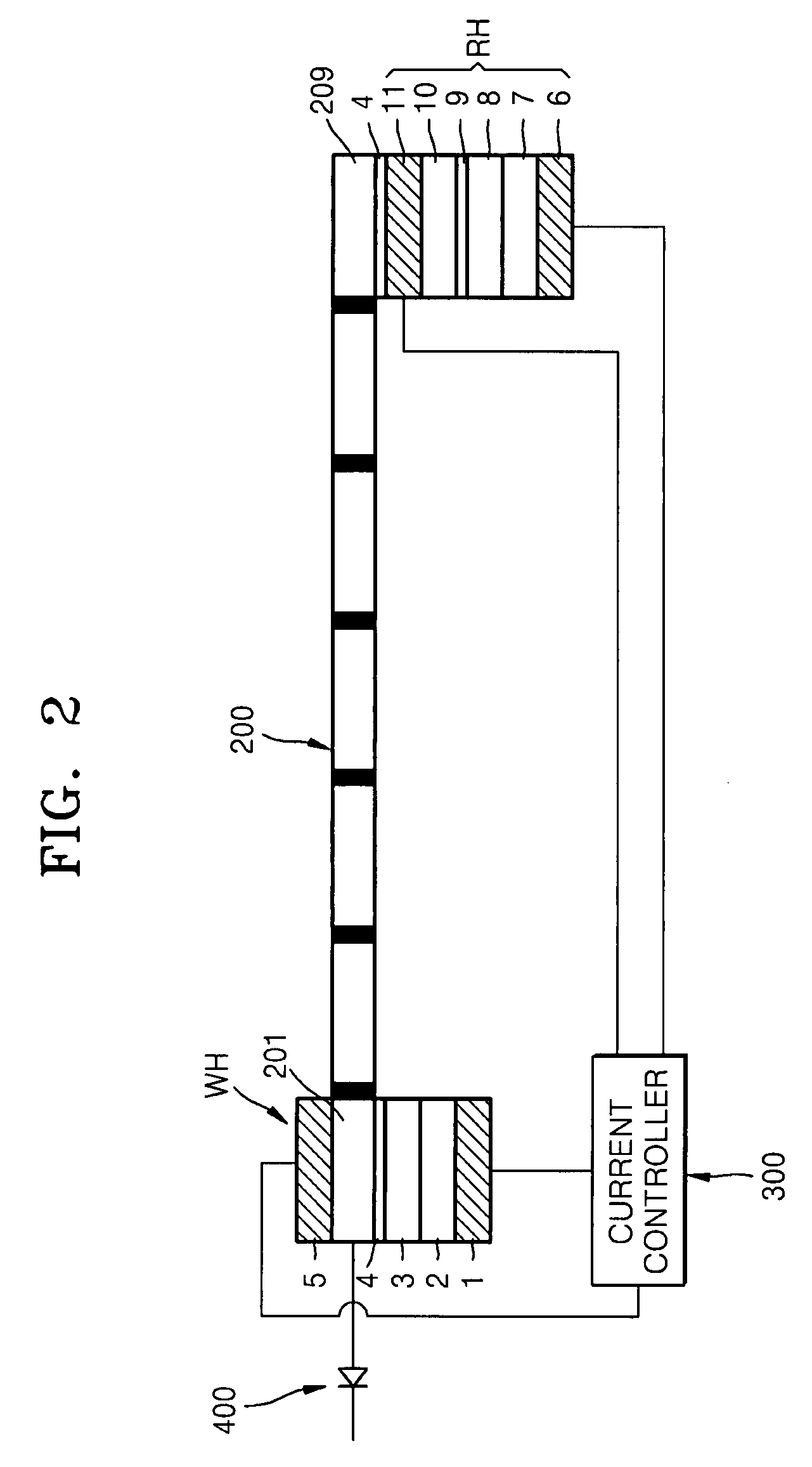
[0047]FIG. 2 is a cross-sectional view of a data storage device using magnetic domain wall movement according to an exemplary embodiment of the present invention. Referring to FIG. 2, a data storage device according to the present embodiment (hereinafter, referred to as “first data storage device”) includes a magnetic layer 200 having a plurality of magnetic domains. In FIG. 2, black portions in the magnetic layer 200 are magnetic domain walls that are boundaries between magnetic domains. The magnetic layer 200 may be of a linear type and notches may be formed on the surface of the magnetic layer 200 to improve stability of the magnetic domain wall movement. The notches may be formed to define magnetic domain areas. The enti...


PUM


Abstract

A data storage device includes a magnetic layer having a plurality of magnetic domains, a write head provided at an end portion of the magnetic layer, a read head to read data written to the magnetic layer, and a current controller connected to the write head and the read head. A method of operating the data storage device includes reading data of an end portion of the magnetic layer using a read head provided at the end portion of the magnetic layer in which a write head is provided at the other end portion thereof, moving a magnetic domain wall of the magnetic layer by a distance corresponding to the length of one magnetic domain toward the end portion, and writing the read data to the other end portion of the magnetic layer using the write head and a current controller provided between the write head and the read head.

Description

CROSS-REFERENCE TO RELATED PATENT APPLICATIONS[0001]This application claims priority from Korean Patent Application No. 10-2006-0096395, filed on Sep. 29, 2006, in the Korean Intellectual Property Office, the disclosure of which is incorporated herein in its entirety by reference.BACKGROUND OF THE INVENTION[0002]1. Field of the Invention[0003]Apparatuses and methods consistent with the present invention relate to a data storage device and a method of operating the data storage device, and more particularly, to a data storage device using magnetic domain wall movement of a magnetic material and a method of operating the data storage device.[0004]2. Description of the Related Art[0005]A magnetic minute area included in a ferromagnetic body is referred to as a magnetic domain. The direction of a magnetic moment is identical in the magnetic domain. The size and magnetization direction of the magnetic domain can be appropriately controlled by the properties, shape and size of the magneti...

Claims


Application Information

Patent Timeline
Patent Type & Authority Patents(United States)
IPC IPC(8): G11C11/14
CPCG11B5/255G11C11/14G11C19/0841Y10S977/933Y10S977/935G11B5/012G11B5/02
Inventor KIM, YONG-SU
Owner SAMSUNG ELECTRONICS CO LTD
Learn More