
Opening-force-maximizing device of an underpressure-activated valve for a drinking container

a technology of underpressure activation and opening force, which is applied in the direction of drinking vessels, tubular containers, functional valve types, etc., can solve the problems of disproportionate suction force, limited membrane diameter, and inability to solve, and achieve the effect of sufficient storage energy and certain resistance to radial deflection

Active Publication Date: 2010-08-17
SMARTSEAL AS
View PDF6 Cites 17 Cited by
  • Summary
  • Abstract
  • Description
  • Claims
  • Application Information

AI Technical Summary

Benefits of technology

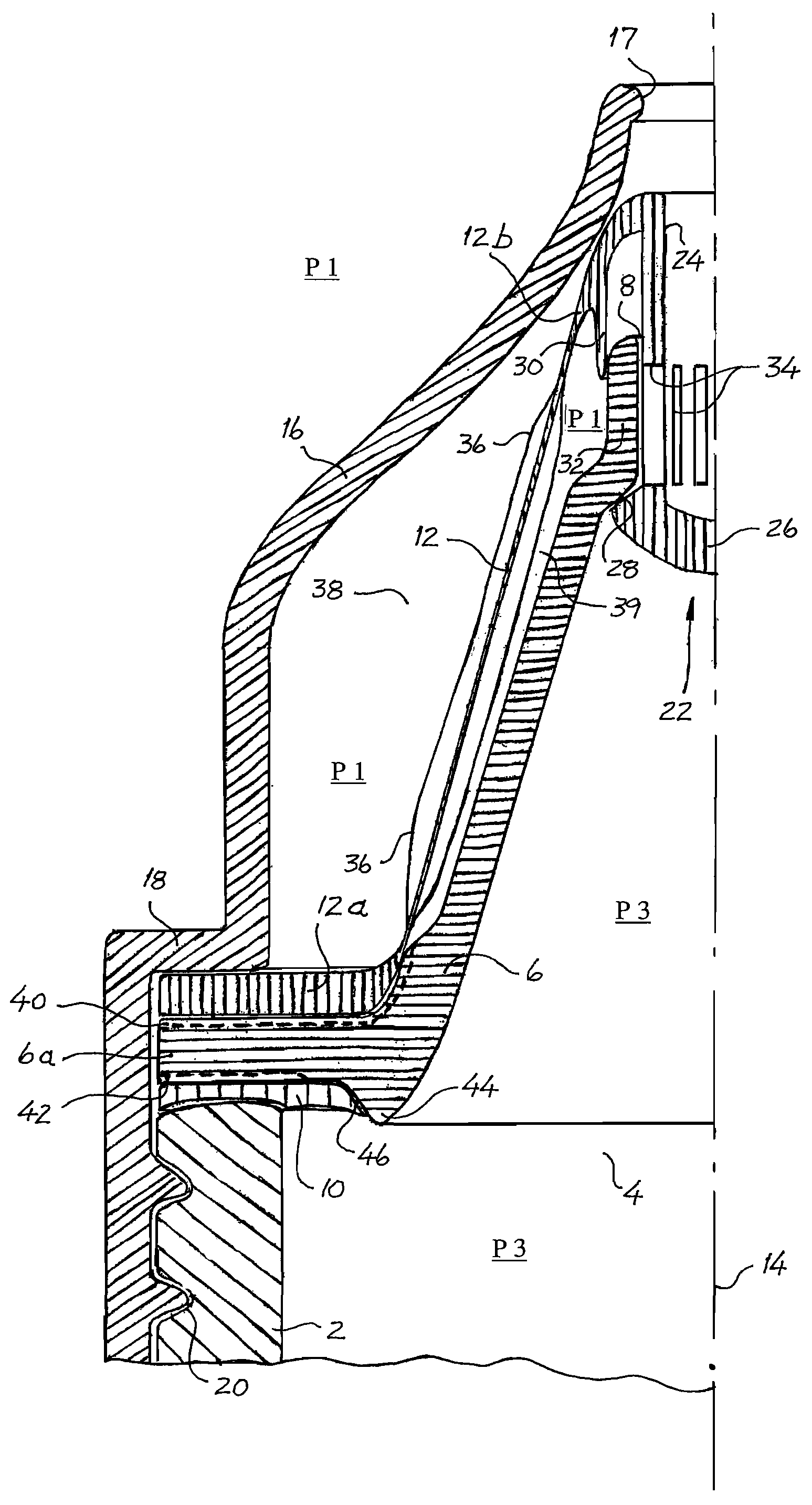
[0012]The present valve device is special in that it is arranged to transmit the largest opening force to the valve sealing member during the incipient phase of the valve-opening, even if the user employs a moderate underpressure to activate the valve device. This effect makes the valve user-friendlier, especially when the sealing member must open against an overpressure in the drinking container. When consuming carbonated drinks, for example, the pressure at the opening instant will always be larger than that of the following drinking phase. The valve device is also advantageous to persons having little suction force, including small children and some categories of disabled and sick persons.
[0023]Inasmuch as the present membrane structure is provided with longitudinal extent axially, this implies that the effective, pressure-responsive area of the membrane may be increased by means of increasing the longitudinal extent of the membrane, but without increasing its radial extent. Thereby, the pressure force on the membrane may be increased without expanding the membrane radially. This is favourable in standard bottle caps, in which the radial extent of the membrane is limited by the cap diameter.
[0031]The membrane may also be braced axially by being arranged with a certain axial rigidity, for example by means of axially extending corrugations or folds, yielding a certain resistance to radial deflection. Thereby, the membrane may exert a firm closing force on the sealing member when the membrane is at rest in its inactive position, in which the valve is in its closed position. If the membrane also is provided with an adapted elastic rigidity through appropriate choice of membrane material and geometric shape, an activated membrane will also possess sufficient stored energy in the form of resiliency to be able to push the sealing member back into its valve-closing position when the underpressure acting on the membrane ceases. Thus, the membrane may be provided with one or more axial braces. For this purpose, the membrane, when viewed in cross-section, may also be arranged into a hexagonal shape, a star shape, a wave shape etc., which has an axial bracing effect. Alternatively, the sealing member may be connected to a separate spring element urging the sealing member pressure-sealingly towards said opening in the partition wall of the valve device when the membrane is in its position of rest.

Problems solved by technology

However, such a solution is not possible when used in standard bottle caps, in which the membrane diameter is limited by the cap diameter.
However, the user must use a disproportionately large suction force, especially during incipient opening of the valve when the drinking can is pressurized.
This valve device may not be perceived as being very functional and user-friendly.
Moreover, this membrane structure is not provided with bracing elements that concentrate and transmit the membrane pressure force to the valve sealing member.
Nor is the membrane structure arranged with any opening-force-maximizing device that limits the incipient suction force required during valve-opening of a pressurized drinking can.
Its liquid contents thus will flow out of the can unintentionally.
However, this further weakens the functionality and user-friendliness of the valve.
In connection with ordinary bottle caps and carbonated drinks, the main problem of this membrane structure therefore lies in its effective membrane area being too small to provide sufficient valve opening force, especially in the opening phase of the valve.
For this reason, the valve device according to U.S. Pat. No. 6,290,090 will be experienced as not being very functional and not being very user-friendly.

Method used


Image

  • Opening-force-maximizing device of an underpressure-activated valve for a drinking container
  • Opening-force-maximizing device of an underpressure-activated valve for a drinking container
  • Opening-force-maximizing device of an underpressure-activated valve for a drinking container

Examples


second embodiment

[0049]the valve device according to the invention is shown in FIG. 2a and FIG. 2b. Wherever possible, the same reference numerals have been used for like parts with the addition of the prefix “1”. Also this valve device is provided with a peripherally continuous, conically shaped membrane 112, which, as opposed to the previous membrane 12, is arranged for inward radial movement upon underpressure-activation. Therefore, the suction chamber 138 is placed on the inside of the membrane 112, whereas its pressure equalizing chamber 139 is placed on the outside thereof. The partition wall 106 is cylindrically shaped to allow the membrane 112 to move radially when activated. The admission of air into the suction chamber 138 takes place through radial venting grooves 140 formed on the outside of the attachment end 112a of the membrane 112. An axially movable sealing member 122 is connected to the maneuvering end 112b of the membrane 122. The sealing member 112 consists of a axially extending...

third embodiment

[0050]the valve device according to the invention is shown in FIG. 3a and FIG. 3b. Wherever possible, the same reference numerals have been used for like parts with the addition of the prefix “2”. Also this valve device is arranged for inward, radial movement and operates essentially in the same manner as the previous valve device. The device according to FIG. 3a and FIG. 3b, however, is provided with a membrane 212 consisting of a cylindrical membrane portion 260 proximate its attachment end 212a and a conical membrane portion 262 proximate its maneuvering end 212b, cf. FIG. 3a. To provide the membrane 212 with a desired deflection profile upon activation, it is provided with a peripheral bracing ring 264 positioned between said membrane portions 260, 262. FIG. 3b shows the membrane 212 activated and deflected inwards towards the valve axis 14. The cylindrical membrane portion 260 is deflected the most and provides the largest axial membrane contraction. The device is arranged with...


PUM


Abstract

An opening-force-maximizing device of an underpressure-activated valve for a drinking container (2). The device includes a partition wall (6, 106, 206) enclosing an outlet opening (4) and being provided with a wall opening (8, 108, 208) in pressure-sealing contact with an axially movable valve sealing member (22, 122, 222) being in position of rest. It also includes a continuous membrane (12, 112, 212) being arranged to the container (2) and about a valve axis (14) through the wall opening (8, 108, 208). The membrane (12, 112, 212) has an axial extent and consists of an attachment end (12a, 112a, 212a) fixedly connected to the partition wall (6, 106, 206), and a movable maneuvering end (12b, 112b, 212b) placed at an axial distance from the attachment end (12a, 112a, 212a). The maneuvering end (12b, 112b, 212b) is arranged in a tensile-force-transmitting manner to said sealing member (22, 122, 222). By arranging the membrane (12, 112, 212) with a maximum longitudinal extent when at rest in its inactive position, and by being arranged radially flexible and deflectable and also being arranged in a manner inhibiting axial stretching, a maximum valve opening force is achieved when underpressure-activated.

Description

CROSS REFERENCE TO RELATED APPLICATION[0001]The present application is the U.S. national stage application of International Application PCT / NO2003 / 000361, filed Oct. 29, 2003, which international application was published on May 13, 2004 as International Publication WO 2004 / 039690. The International Application claims priority of Norwegian Patent Application 20025193, filed Oct. 29, 2002.BACKGROUND OF THE INVENTION[0002]The present invention relates to an opening-force-maximizing device of an underpressure-activated, self-adjusting valve for a drinking container. The container may contain a pressurized or non-pressurized soft drink or other liquefied article of food. The device is intended for use in connection with a drinking spout for the container.[0003]Underpressure-activated devices for automatic opening of drinking valves are known from previous patent publications, including U.S. Pat. No. 6,290,090. The opening mechanism according to U.S. Pat. No. 6,290,090 includes a pressur...

Claims


Application Information

Patent Timeline
IPC IPC(8): A47G19/22B65D35/38B65D47/24
CPCB65D47/248Y10T137/7722
Inventor NAESJE, KJETIL
Owner SMARTSEAL AS
Learn More