
High-resolution, continuous field-of-view (FOV), non-rotating imaging system

a cmos imaging and high-resolution technology, applied in the field of electronic imaging systems, can solve the problems of large amount of data, inefficient way of carrying out diverse tasks, and side walls acting as visual blockages, and achieve the effect of high resolution

Inactive Publication Date: 2010-08-10
ADMINISTATOR OF THE NAT AERONAUTICS & SPACE ADMINISTATOR U S GOVERNMENT AS REPRESENTED BY THE
View PDF11 Cites 202 Cited by
  • Summary
  • Abstract
  • Description
  • Claims
  • Application Information

AI Technical Summary

Benefits of technology

[0013]It is a primary object of this invention to provide an improved high resolution CMOS imaging system especially suitable for use in a periscope head that yields a continuous 360-degree field-of-view without mechanical rotation.

Problems solved by technology

However, since each periscope has a limited field of view and one or both side walls of each periscope will always be visible, these visible side walls will act as visual blockages.
Additionally, whenever multiple imagers are employed the amount of data complicates the issue.
The use of an optical zoom is one way, but an extremely inefficient way of carrying out these diverse tasks because it cannot simultaneously provide narrow and wide field of view scene visualization.
It is often difficult for an operator to quickly zoom in and out of the ROI because of the vast changes in the FOV during zooming and relocating contacts within the search FOV (which may be 50× higher magnification).

Method used


Image

  • High-resolution, continuous field-of-view (FOV), non-rotating imaging system
  • High-resolution, continuous field-of-view (FOV), non-rotating imaging system
  • High-resolution, continuous field-of-view (FOV), non-rotating imaging system

Examples


Embodiment Construction

[0022]The present invention is a high resolution CMOS imaging system especially suitable for use in a periscope head that yields an autonomously-stitched and seamlessly-continuous 360-degree field-of-view image with autonomously and / or manually selected magnified subwindow regions of interest, without any mechanical rotation.

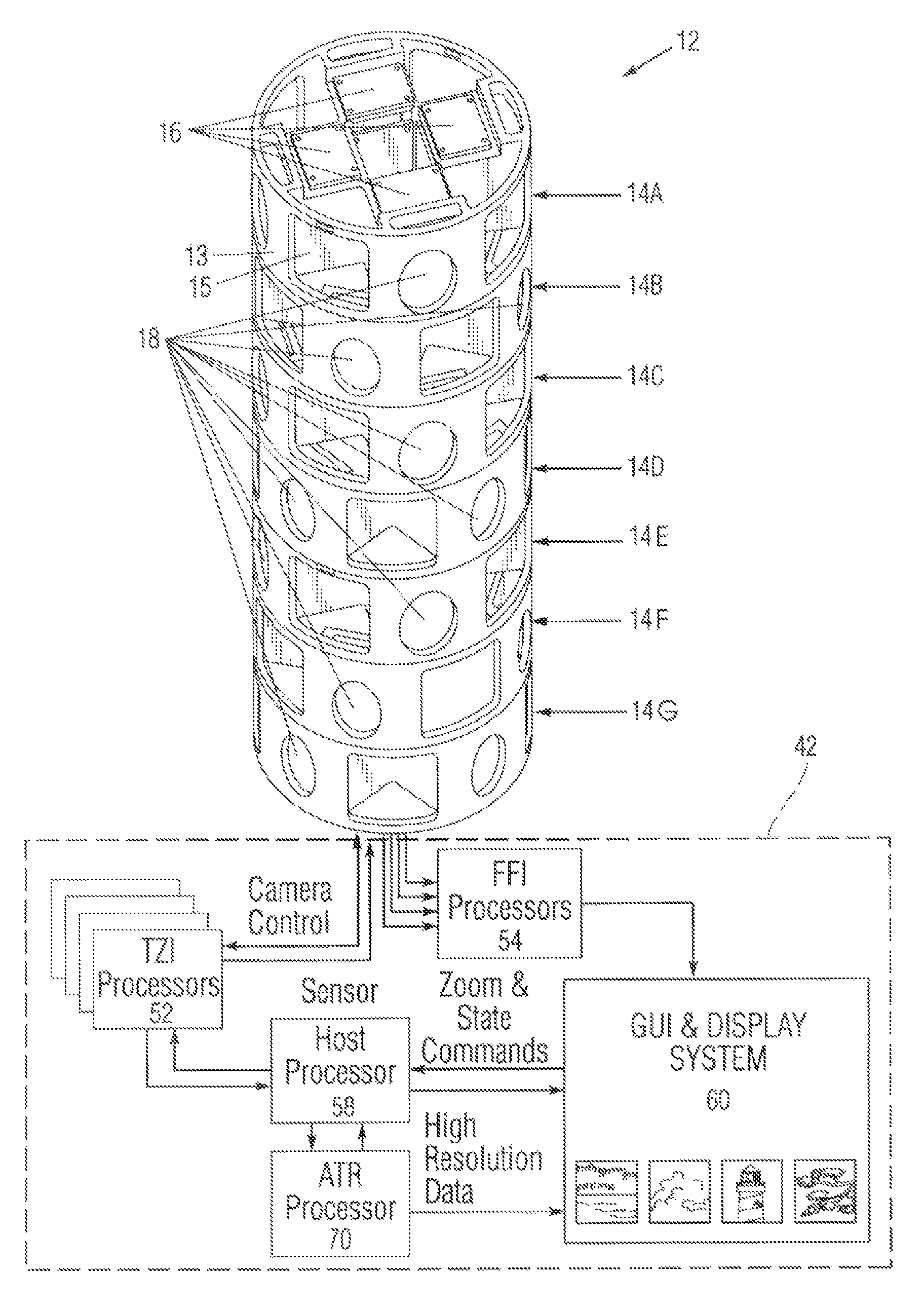
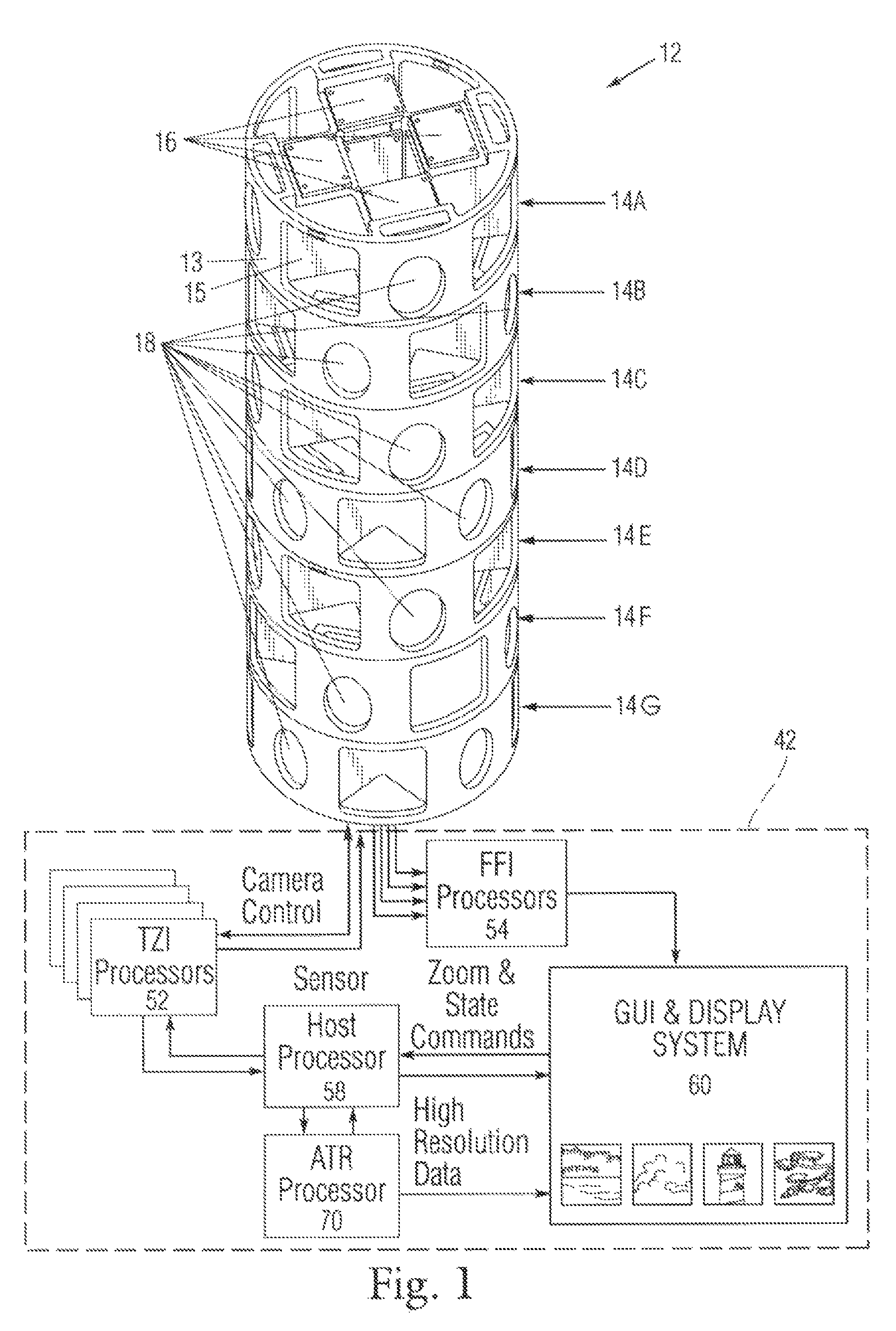
[0023]FIG. 1 is a perspective view of the system architecture including major components and data paths.

[0024]The high resolution CMOS imaging system comprises two major components: a sensor head 12 for scene acquisition, and a control apparatus 42 inclusive of distributed processors and software for device-control, data handling, and display.

[0025]The sensor head 12 is a uniquely-configured cylindrical head assembly suitable for use on the existing mast of conventional periscopes inside a full length sealed cylindrical outer casing. The sensor head 12 further comprises a multi-deck imaging array with seven (7) cylindrical decks 14A-G stacked end-to-end. Structu...


PUM


Abstract

A high resolution CMOS imaging system especially suitable for use in a periscope head. The imaging system includes a sensor head for scene acquisition, and a control apparatus inclusive of distributed processors and software for device-control, data handling, and display. The sensor head encloses a combination of wide field-of-view CMOS imagers and narrow field-of-view CMOS imagers. Each bank of imagers is controlled by a dedicated processing module in order to handle information flow and image analysis of the outputs of the camera system. The imaging system also includes automated or manually controlled display system and software for providing an interactive graphical user interface (GUI) that displays a full 360-degree field of view and allows the user or automated ATR system to select regions for higher resolution inspection.

Description

CROSS-REFERENCE TO RELATED APPLICATIONS[0001]The present application derives priority from U.S. Provisional Patent Application No. 60 / 797,742; Filed May 3, 2006.STATEMENT OF GOVERNMENT INTEREST[0002]The invention described hereunder was made in the performance of work under a NASA contract, and is subject to the provisions of Public Law #96-517 (35 U.S.C. 202) in which the Contractor has elected not to retain title.BACKGROUND OF THE INVENTION[0003]1. Field of the Invention[0004]The present invention relates to electronic imaging systems and, more particularly, to a high resolution CMOS imaging system especially suitable for use in a periscope head that yields a continuous 360-degree field-of-view without mechanical rotation.[0005]2. Description of Prior Art[0006]A periscope “head” is the top portion of a periscope that contains the lenses and mirrors used to observe what is outside certain vehicles, including submarines, armored cars, spacecraft and their rovers.[0007]Conventional p...

Claims


Application Information

Patent Timeline
Patent Type & Authority Patents(United States)
IPC IPC(8): H04N5/225H04N7/18
CPCG08B13/19626H04N5/2252H04N5/2254H04N5/2258H04N5/232H04N5/23216H04N5/23238H04N7/181H04N23/51H04N23/55H04N23/45H04N23/62H04N23/698H04N23/631
Inventor HUNTSBERGER, TERRANCE L.STIRBL, ROBERT C.AGHAZARIAN, HRANDPADGETT, CURTIS W.
Owner ADMINISTATOR OF THE NAT AERONAUTICS & SPACE ADMINISTATOR U S GOVERNMENT AS REPRESENTED BY THE
Learn More