
Exercise device with footboards having tubular support

a technology of exercise device and footboard, which is applied in the field of exercise device, can solve the problems of limiting the usefulness of these devices, correspondingly less portable, and difficult for users to frequently employ in multiple exercise locations, and achieves the effects of low weight, high portability, and small footprin

Inactive Publication Date: 2010-08-10
REAMS TERRY
View PDF19 Cites 32 Cited by
  • Summary
  • Abstract
  • Description
  • Claims
  • Application Information

AI Technical Summary

Benefits of technology

[0011]The present invention is directed to an exercise apparatus that has a relatively small size, low weight, and small footprint, and is therefore highly portable. In particular, the base of the present invention is formed by means of a tube. The superior strength provided by the tubular form allows the utilization of a base that is of relatively small size and weight compared to other exercise devices, while still providing sufficient strength to support the device despite the stress caused by frequent use.
[0014]It is a further object of the present invention to provide for an exercise apparatus that has a low weight.
[0016]It is also an object of the present invention to provide an exercise apparatus that is highly portable.

Problems solved by technology

The large size, large weight, and shape of the base of these devices limits their usefulness, since compactness and portability are known to be critical in encouraging persons to purchase and regularly use exercise equipment.
Since these devices are attached to or integrated into a chair, they are correspondingly less portable than a similar free-standing exercise device, and would be difficult for a user to frequently employ in multiple exercise locations unless multiple such devices were purchased.
Each of the devices discussed above is either integrated with or mounted to another piece of furniture—particularly a chair—or requires a relatively large amount of floorspace due to the large “footprint” of the device.
The large size and weight results in a lack of portability of such devices, which also discourages their use, particularly by users who must travel between various locations frequently and thus require exercise equipment that is highly portable.

Method used


Image

  • Exercise device with footboards having tubular support
  • Exercise device with footboards having tubular support
  • Exercise device with footboards having tubular support

Examples


Embodiment Construction

)

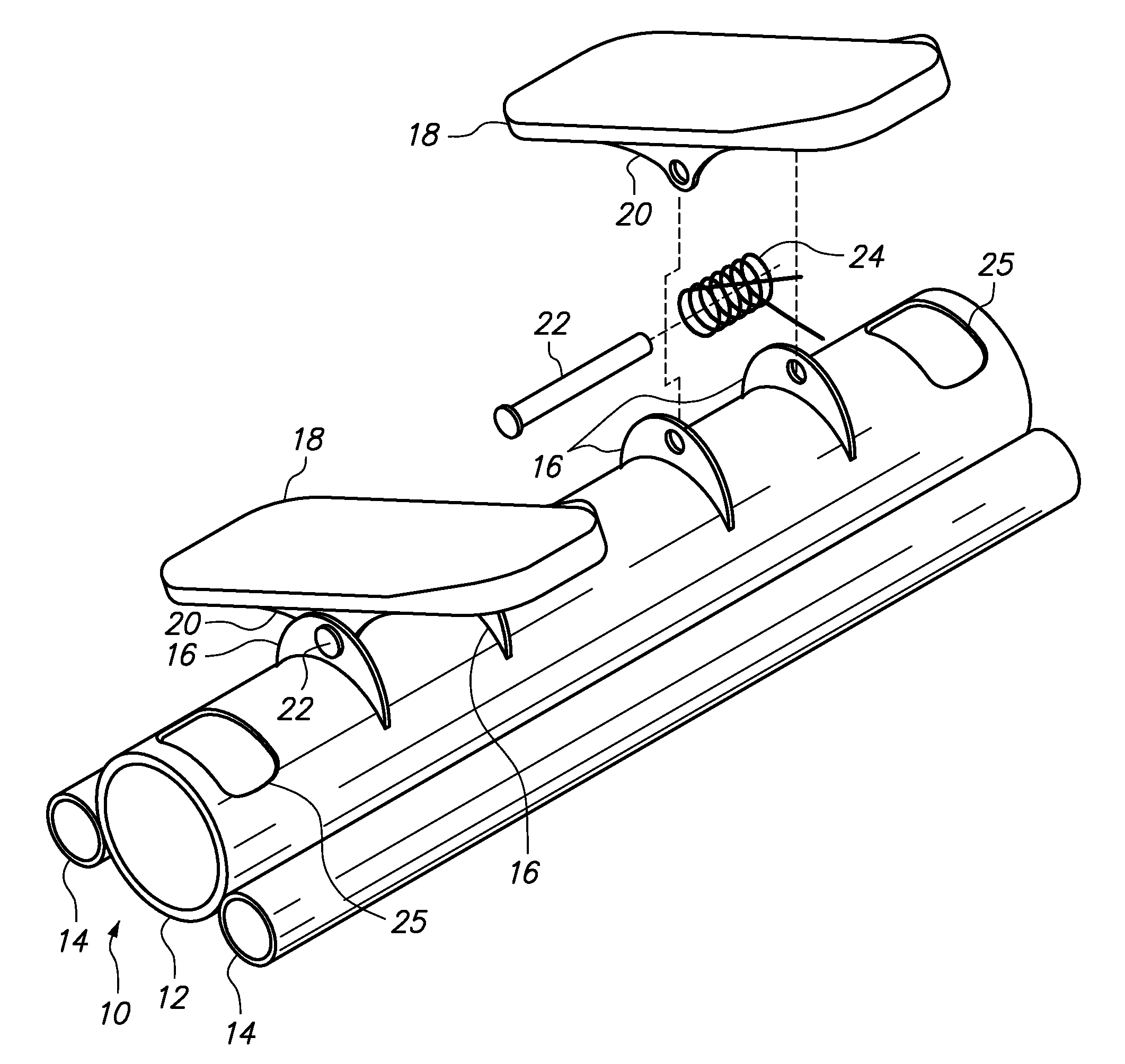
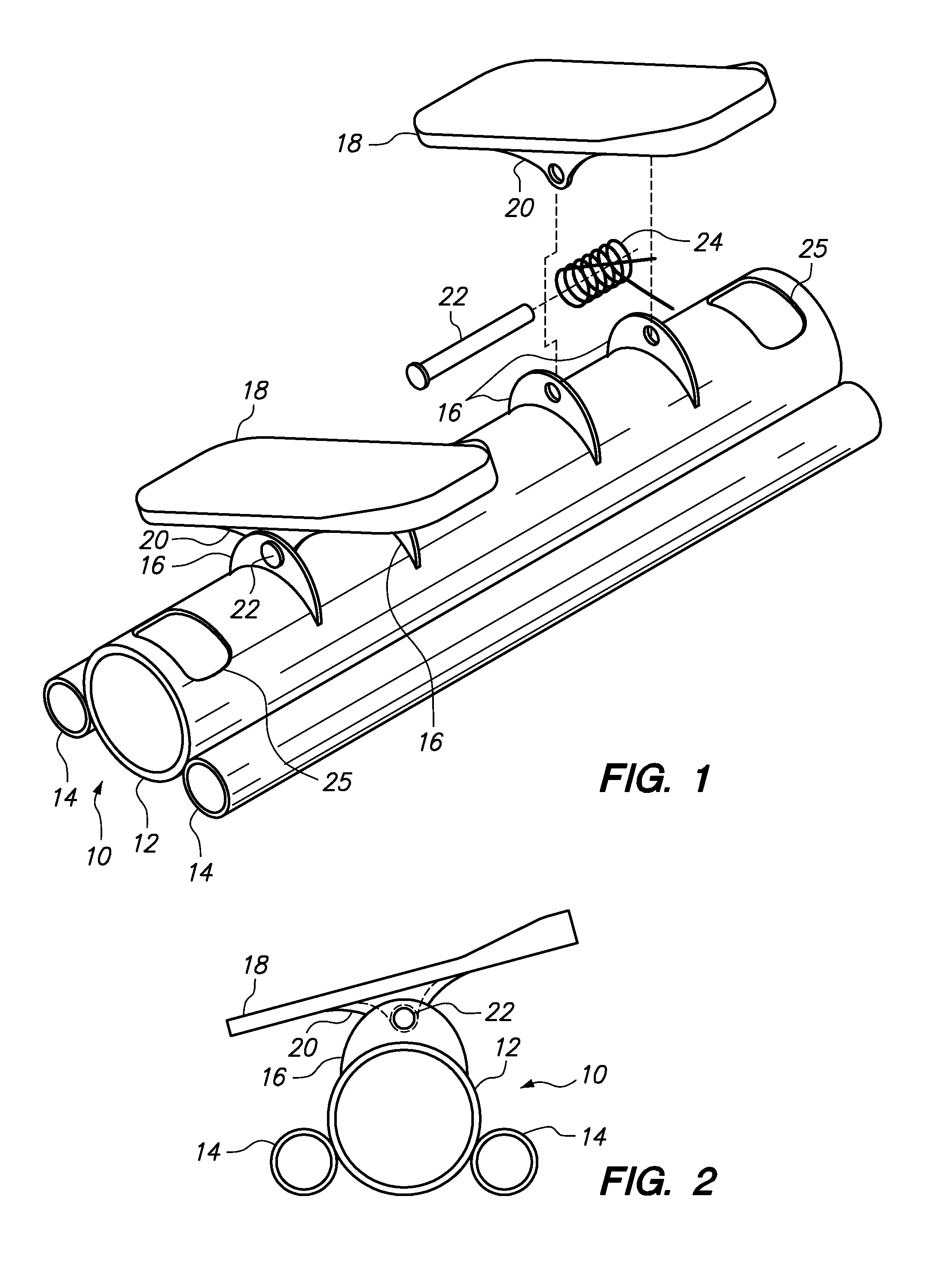
[0025]With reference to FIGS. 1-2 and 7, a first preferred embodiment of the present invention may be described. Base 10 is formed of three tubes, a center tube 12 and two side tubes 14. Tubes 12 and 14 are preferably hollow in order to lower the weight of base 10, although they may be solid in alternative embodiments. Tubes 12 and 14 may be formed of any sufficiently strong and light material, aluminum being used in the preferred embodiment. Tubes 12 and 14 may be connected by any conventional means, welding being the preferred method of joining the tubes for strength, and to avoid the additional weight that would be incurred by the use of metal fasteners such as bolts and nuts.

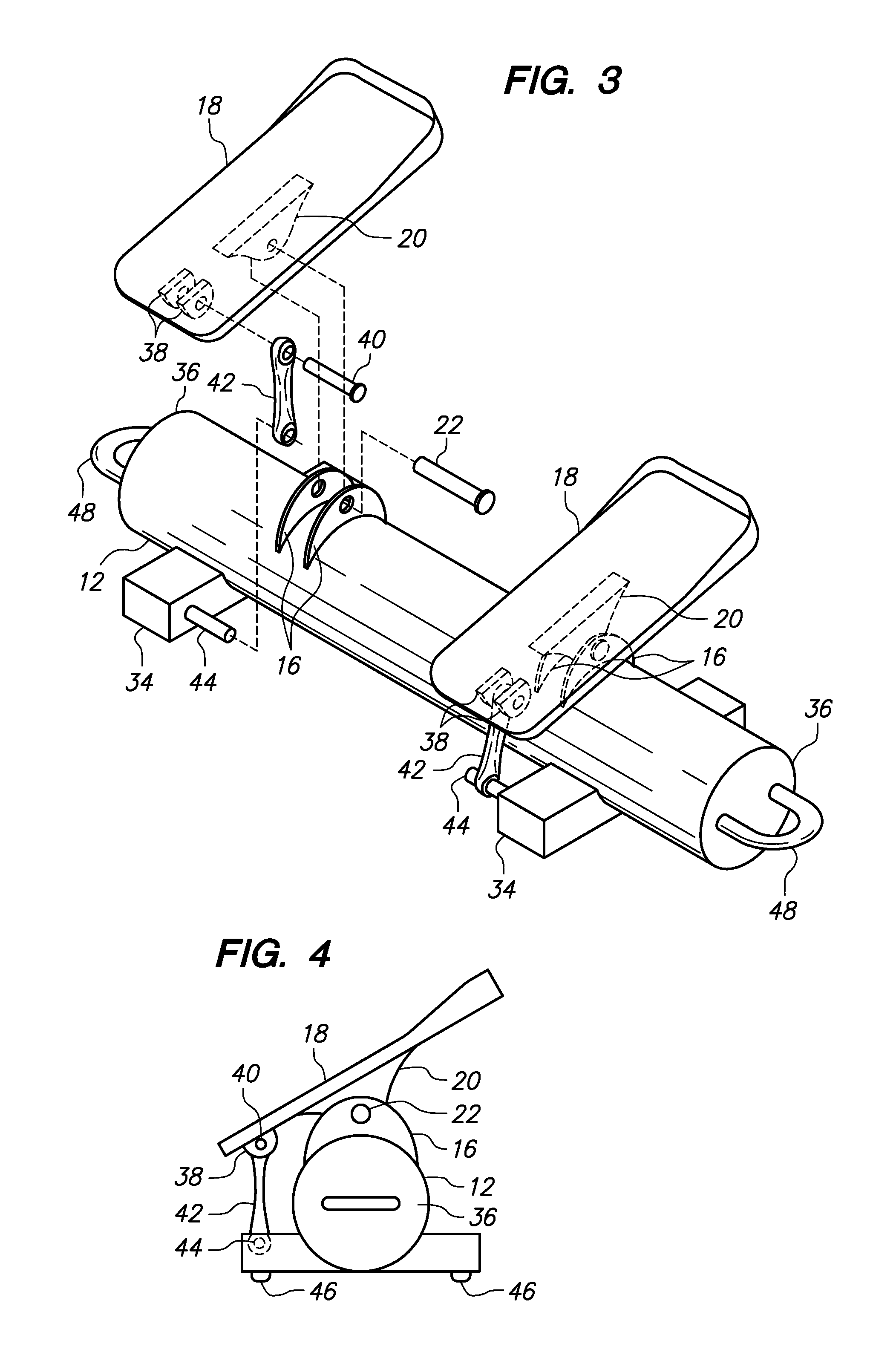
[0026]Four tube flanges 16 are attached perpendicularly to tube 12. Tube flanges 16 may preferably be attached as by welding. Alternatively, tube flanges 16 may be formed integrally with tube 12 in the molding process. Each of the two footboards 18 have a pair of footboard flanges 20 extending perpendicular...


PUM


Abstract

An exercise device comprises a tubular support with attached pivoting footboards. The footboards are biased such that pressing the footboards forward causes an exercise effect in the user's lower body. Resilient cords may be used that are attached to the device, such that pulling the handles attached to the resilient cords causes an exercise effect in the user's lower body. The tubular construction of the support allows the device to be constructed in such a manner as to reduce its weight and footprint, and increase its portability, over other exercise devices providing comparable exercise opportunities.

Description

CROSS-REFERENCE TO RELATED APPLICATIONS[0001]Not applicable.STATEMENT REGARDING FEDERALLY SPONSORED RESEARCH OR DEVELOPMENT[0002]Not applicable.BACKGROUND OF THE INVENTION[0003]1. Field of the Invention[0004]The present invention relates to exercise devices, and in particular to exercise devices that incorporate pivoting footboards.[0005]2. Brief Description of the Related Art[0006]The art contains a number of examples of exercise or training devices that utilize pivoting footboards. For example, U.S. Pat. No. 3,741,540 to Shimizu teaches a “nether limbs training implement” with spring-loaded footboards. The footboards are supported by a large, flat base block. U.S. Pat. No. 5,755,651 to Homyonfer et al. teaches a leg exercise device with at least one pivoting plate member. The pivoting members are supported by a large, four-sided, rectangular base. U.S. Pat. No. 5,267,923 to Piaget et al. teaches a foot exercise device that operates by pneumatic means using foot treadles. Again, th...

Claims


Application Information

Patent Timeline
IPC IPC(8): A63B23/08A63B21/02A63B21/04
CPCA63B21/0552A63B23/03541A63B23/0429A63B21/0421A63B21/0442A63B21/0557A63B23/03575A63B23/085A63B23/12A63B21/4034
Inventor REAMS, TERRY
Owner REAMS TERRY
Learn More