
Method and apparatus for machining deep hole

a deep hole and deep hole technology, applied in the direction of turning machine accessories, manufacturing tools, transportation and packaging, etc., can solve the problems of difficult discharge of shavings, difficult to reach the tip of the gun drill bit, and large scattering of coolant, so as to improve the flow rate of coolant, prevent the effect of coolant scattering and efficient discharg

Inactive Publication Date: 2010-08-10
TOSHIBA MASCH CO LTD
View PDF11 Cites 8 Cited by
  • Summary
  • Abstract
  • Description
  • Claims
  • Application Information

AI Technical Summary

Benefits of technology

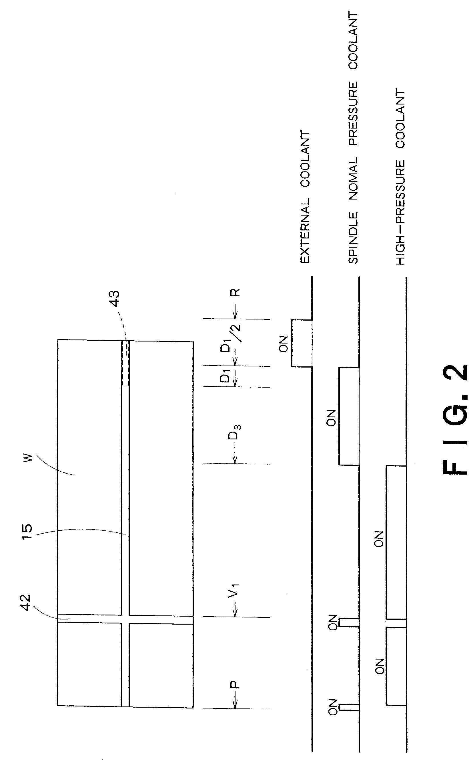
[0008]It is therefore an object of the invention to provide a method and apparatus for machining a deep hole, which solves the above problems in the prior art and enables prevention of scattering of a coolant and efficient discharge of shavings by switching the pressure of a coolant between a high pressure and a normal pressure, increasing the flow rate of a coolant, or selectively using an internal coolants which is fed through an internal passage of a gun drill, and an external coolant which is jetted from outside the gun drill, according to the stage of progress of machining of a deep hole.
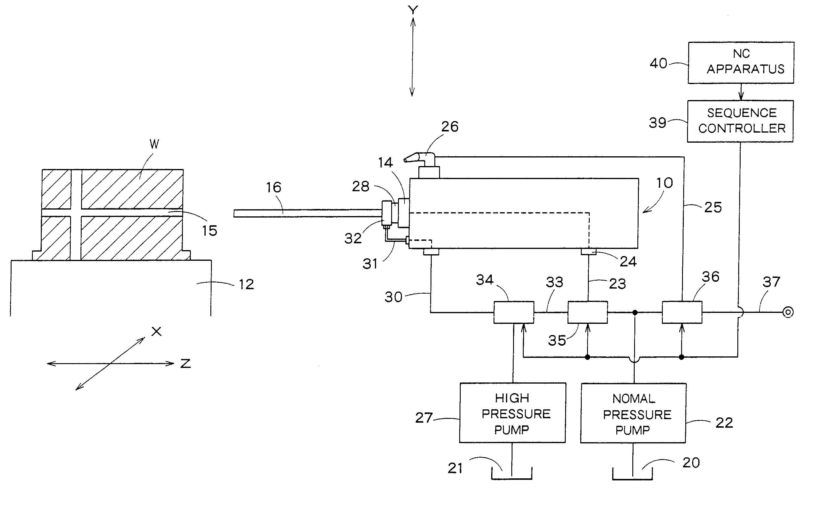
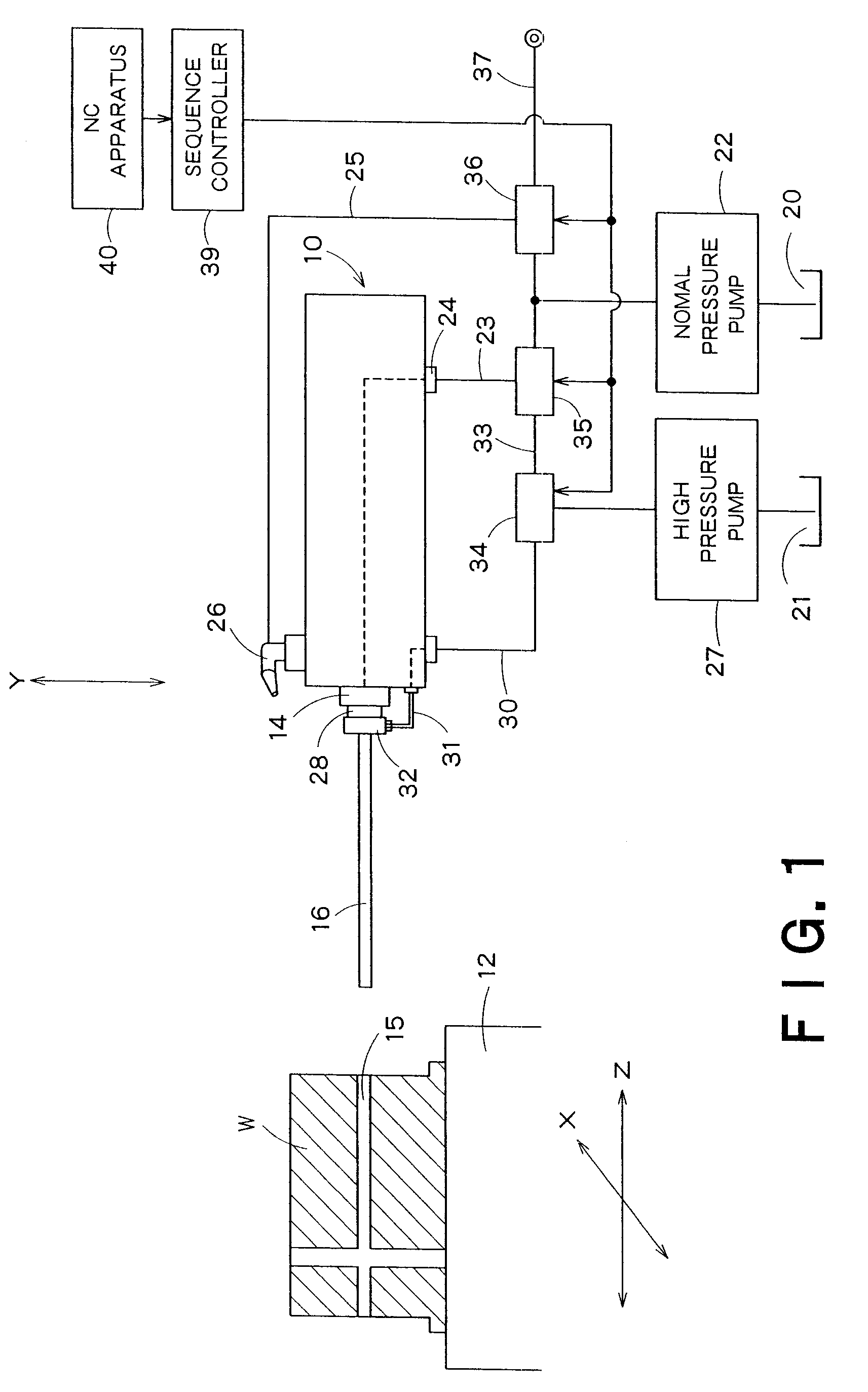
[0010]The present invention also provides an apparatus for machining a deep hole in a workpiece with a gun drill mounted to a spindle, said apparatus comprising: an external normal pressure coolant supply line for supplying a coolant at a normal pressure to a nozzle provided outside the spindle; a spindle normal pressure coolant supply line for supplying a coolant at a normal pressure to a coolant passage passing in the interior of the spindle and extending to the tip of the gun drill; a high-pressure coolant supply line which joins the coolant passage in the spindle and supplies a coolant, whose pressure is higher than the normal pressure, to the coolant passage; line switching means for selectively opening and closing the spindle normal pressure coolant supply line, the external normal pressure coolant supply line and the high-pressure coolant supply line either singly or in any combination; and a sequence controller for performing the opening / closing switching operations of the line switching means in accordance with a process sequence specified by a program. According to the present invention, scattering of a coolant can be prevented and shavings can be discharged efficiently by switching the pressure of a coolant between a high pressure and a normal pressure, increasing the flow rate of a coolant, or selectively using an internal coolant, which is fed through an internal passage of a gun drill, and an external coolant which is jetted from outside the gun drill, according to the stage of progress of machining of a deep hole. Even the deepest hole can be machined while optimizing the supply of a coolant.

Problems solved by technology

Deep hole machining with a gun drill have specific problems: For example, a coolant becomes harder to reach the tip of the gun drill and discharge of shavings becomes difficult as a hole becomes deeper.
This involves the problem of too much scattering of the coolant upon its collision with the workpiece as well as the problem of decrease in the effect of discharging shavings with the progress of machining to a deeper hole.
Especially in the case of a deep hole to be machined in a large-sized mold such as for use in molding of an instrument panel or a bumper of an automobile, it is necessary to use a long gun drill, for example having a length of not less than 70 mm, making it difficult to discharge shavings.

Method used


Image

  • Method and apparatus for machining deep hole
  • Method and apparatus for machining deep hole
  • Method and apparatus for machining deep hole

Examples


Embodiment Construction

[0013]A preferred embodiment of the present invention will now be described with reference to the drawings.

[0014]FIG. 1 shows a deep hole machining apparatus according to an embodiment of the present invention. This embodiment relates to application of the present invention to a horizontal boring machine.

[0015]In FIG. 1, reference numeral 10 denotes the spindle head of the boring machine. The spindle head 10 is vertically-movably mounted to a not-shown column. Reference numeral 12 denotes a table on which a workpiece W is placed. X-axis is an axis for control of movement of the table 12 in the lateral direction, and Y-axis is an axis for control of vertical movement of the spindle head 10. Z-axis is an axis for control of movement of the table 12 in the longitudinal direction.

[0016]The spindle head 10 is provided with a spindle 14 in a horizontal position. When machining a deep hole 15 in the workpiece W, a gun drill 16 as a tool is mounted to the spindle 14. In this embodiment the ...


PUM

PropertyMeasurementUnit
lengthaaaaaaaaaa
lengthaaaaaaaaaa
pressureaaaaaaaaaa

Abstract

There is provided a method for machining a deep hole, which enables prevention of scattering of a coolant and efficient discharge of shavings.The deep hole machining method includes: feeding a spindle to a deep hole machining start position while jetting a coolant toward a workpiece from an external normal pressure coolant supply line; closing the external normal pressure coolant supply line and opening a spindle normal pressure coolant supply line at the start of machining of a deep hole, and machining the deep hole to a predetermined intermediate depth while supplying a coolant to a machining point; and closing the spindle normal pressure coolant supply line and opening a high-pressure coolant supply line when the depth of the hole machined has reached the intermediate depth, and machining the deep hole to the final depth while supplying a high-pressure coolant to a machining point.

Description

BACKGROUND OF THE INVENTION[0001]1. Field of the Invention[0002]The present invention relates to a method and apparatus for machining a deep hole, and more particularly to a method and apparatus for machining a deep hole which, when machining a deep hole in a workpiece with a gun drill, can optimize the supply of a coolant according to the machining stage.[0003]2. Background Art[0004]A drill is generally used in machining of a hole in a workpiece, and a gun drill is widely employed to machine a deep hole in a workpiece. For example, when machining a mold for molding of a large-sized resin product, such as an instrument panel or a bumper of an automobile, deep hole machining with a gun drill is carried out to machine a cooling hole or a slide core hole for insertion of an extrusion pin.[0005]Deep hole machining with a gun drill have specific problems: For example, a coolant becomes harder to reach the tip of the gun drill and discharge of shavings becomes difficult as a hole becomes ...

Claims


Application Information

Patent Timeline
Patent Type & Authority Patents(United States)
IPC IPC(8): B23B35/00B23B41/02
CPCB23B41/02B23B2250/12Y10S408/705Y10T408/03Y10T409/304032Y10T408/46Y10T408/455Y10T408/44B23B41/00B23Q11/10B23Q11/1015B23Q11/1038
Inventor KATOH, KOUICHIITOH, TAKAMASA
Owner TOSHIBA MASCH CO LTD
Learn More