Screen and projector
a projector and projector technology, applied in the field of projectors, can solve the problems of less accurate focusing, reduced light, image quality degradation, etc., and achieve the effect of suppressing the degradation of the viewing angle control function and suppressing the reduction of image quality
- Summary
- Abstract
- Description
- Claims
- Application Information
AI Technical Summary
Benefits of technology
Problems solved by technology
Method used
Image
Examples
first embodiment
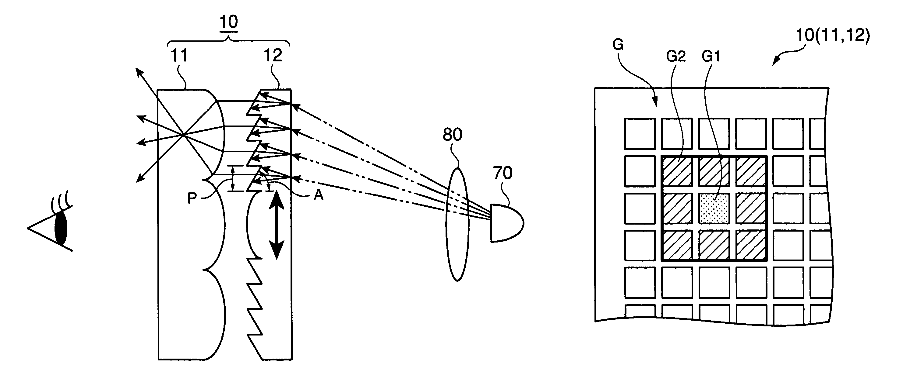
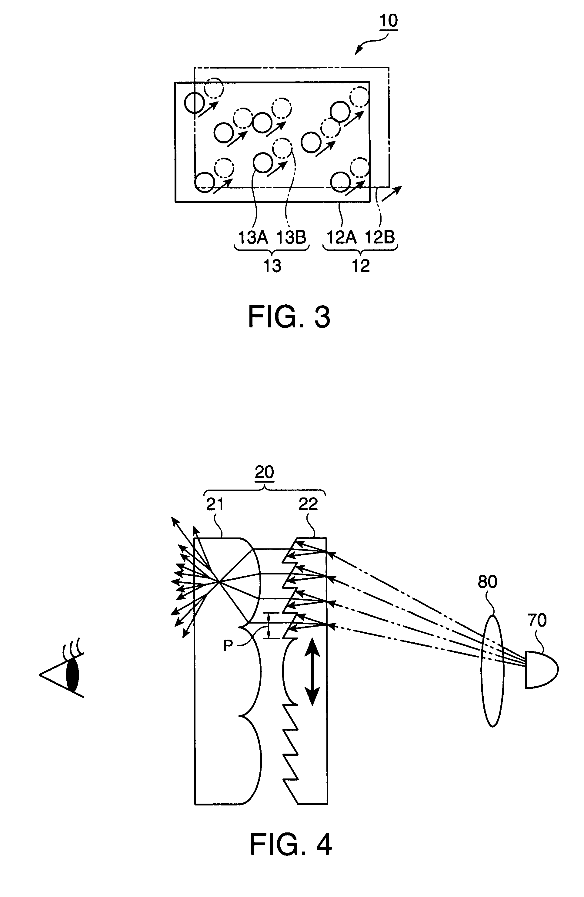
[0028]FIG. 1 is a schematic view showing the relationship between the screen according to a first embodiment of the invention and incident light. FIG. 2 is a schematic view showing the extent within which a second layer moves. FIG. 3 is a schematic view showing the relationship between the motion of the second layer and a speckle pattern generated on the screen. The configuration and operation of the screen 10 will be described with reference to FIGS. 1 to 3.
[0029]As shown in FIG. 1, the screen 10 in this embodiment includes a first layer having viewing angle control means for enlarging the viewing angle and a second layer having angular conversion means for converting the angles of incident light beams having different angles of incident so that the incident light beams are emitted in a substantially same direction. One of the layers has a diffusion capability to diffuse incident light beams. As for the motion of the first and second layers, the one of the layers having the diffusi...
second embodiment
[0053]FIG. 4 is a schematic view showing the relationship between the screen according to a second embodiment of the invention and incident light. The configuration and operation of the screen 20 will be described with reference to FIG. 4.
[0054]As shown in FIG. 4, the screen 20 has the substantially same configuration as that of the screen 10 in the first embodiment except that in the first embodiment, the second layer has the diffusion capability and moves relative to the first layer with no diffusion capability, while in the second embodiment, the first and second layers both have diffusion capabilities. As for the motion of the first and second layers, at least one of the layers moves relative to the other.
[0055]Specifically, the configuration in this embodiment includes a lenticular lens 21 as the first layer having viewing angle control means for enlarging the viewing angle and a Fresnel lens 22 as the second layer having angular conversion means for converting the angles of in...
third embodiment
[0070]FIG. 5 is a schematic side cross-sectional view when the screen according to a third embodiment of the invention is applied to a rear projector. FIG. 6 is a schematic configuration diagram of the screen having moving means.
[0071]The configuration and operation of a rear projector 500 as a projector will be schematically described with reference to FIG. 5.
[0072]As shown in FIG. 5, the rear projector 500 generally includes a cabinet 510 as an external housing, a projector unit 520 as an image projection device, a control unit 530, a reflective mirror 540, a transmissive screen 30, a control circuit 110 that is a component of moving means, and a driver 120.
[0073]The cabinet 510 has a box shape with its back side (right side in FIG. 5) inclined and houses the projector unit 520, the control unit 530, and the reflective mirror 540 therein, as shown in FIG. 5. Although not specifically illustrated, the cabinet 510 houses a power supply unit that supplies power to various components ...
PUM
 Abstract
Description
Claims
Application Information
 - R&D
- Intellectual Property
- Life Sciences
- Materials
- Tech Scout
- Unparalleled Data Quality
- Higher Quality Content
- 60% Fewer Hallucinations
Browse by: Latest US Patents, China's latest patents, Technical Efficacy Thesaurus, Application Domain, Technology Topic, Popular Technical Reports.
© 2025 PatSnap. All rights reserved.Legal|Privacy policy|Modern Slavery Act Transparency Statement|Sitemap|About US| Contact US: help@patsnap.com


