
Luminaire comprising a spotlight and adjustable holding device for a spotlight

Inactive Publication Date: 2010-07-27
ZUMTOBEL LIGHTING GMBH & CO KG
View PDF10 Cites 23 Cited by
  • Summary
  • Abstract
  • Description
  • Claims
  • Application Information

AI Technical Summary

Benefits of technology

[0004]The invention is now based on the object of designing a luminaire according to the preamble of claim 1 or a holding device according to the preamble of claim 4 in such a way that it can be adjusted with easy manipulation.
[0006]In the case of the luminaire according to claim 1, there is disposed in the spotlight housing a release device which can be used to reduce or remove the clamping force of the clamping device, the release device being accessible from outside the spotlight housing in order that it can be operated manually. It is thereby possible, through manual operation, to remove the clamping force of the clamping device, or at least to reduce it to such an extent that it is possible to adjust the spotlight with easy manipulation in a manner that does not damage the clamping device or the articulated joint. This design thus enables the spotlight to be adjusted with easy manipulation in a non-damaging manner. A long service life is thus achieved, because wear is prevented or at least reduced.
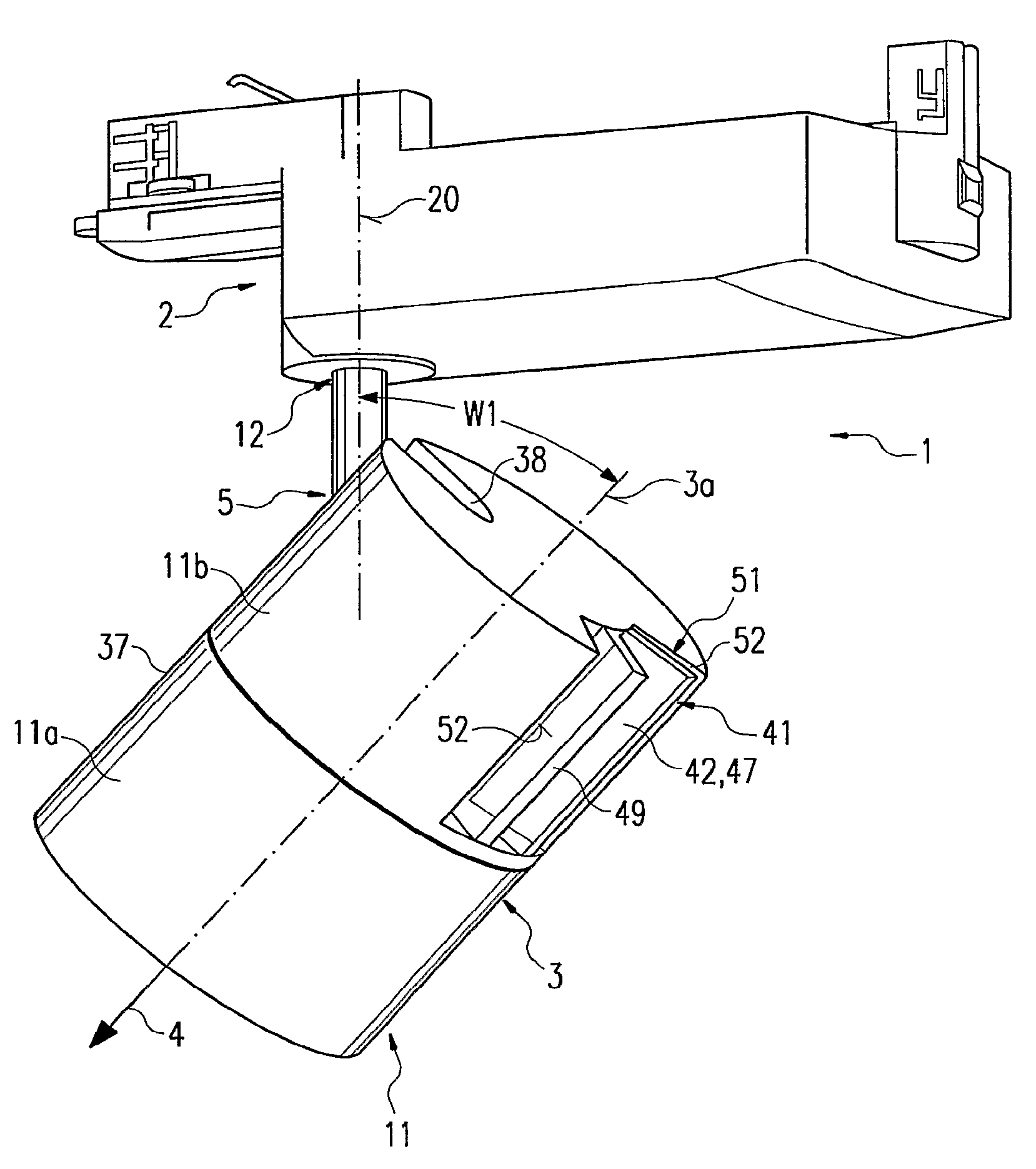
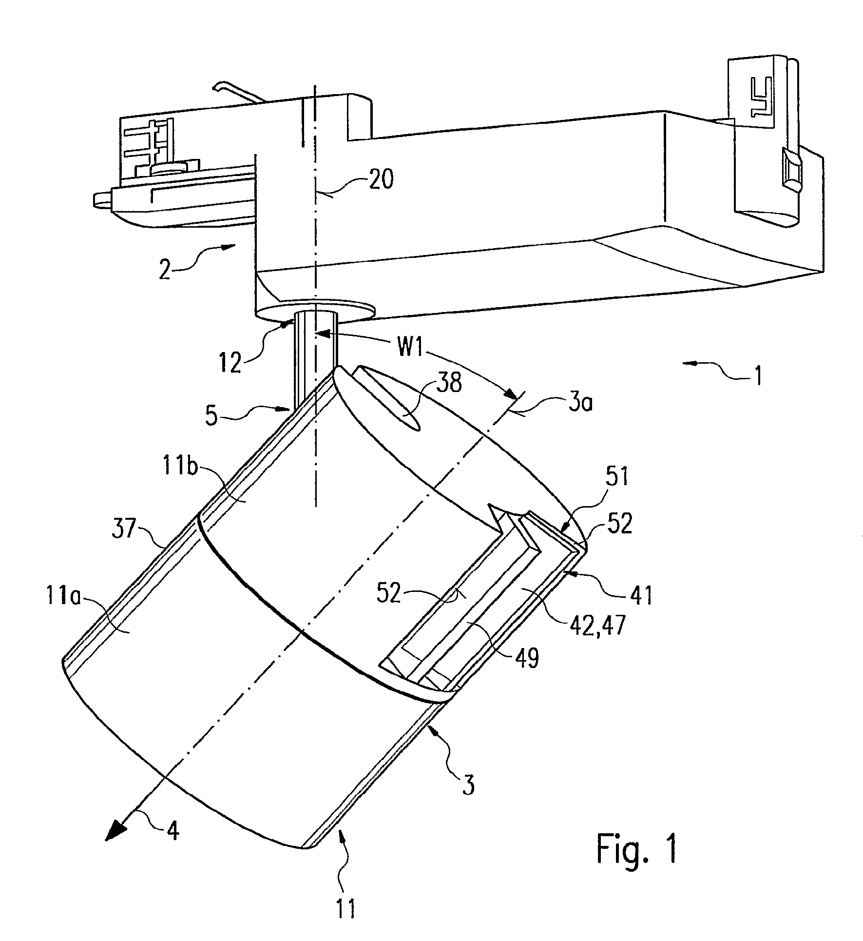
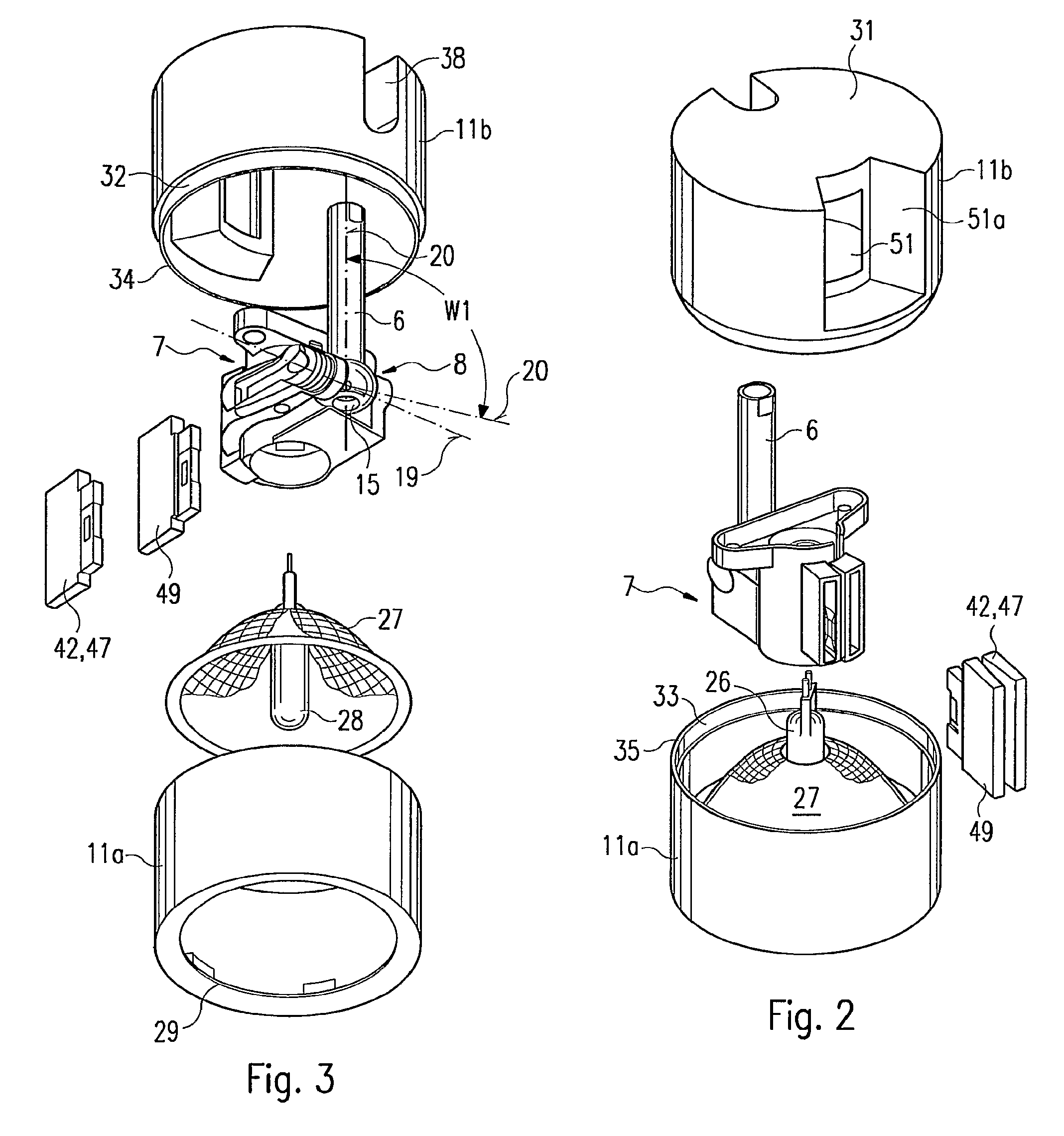
[0007]The particular ease of manipulation is achieved, according to the invention, in that manual operation of the release device can be effected directly from outside the spotlight housing. This is effected by means of an actuating element which is accessible from the outside and is disposed, for example, in an aperture of the spotlight housing, said actuating element being such that it can be manually gripped and actuated in a direct manner, and being disposed at a distance next to a supporting element which is solid with the housing. This design makes it possible to grip both elements, for example with two fingers of the operating hand, and thereby to move the actuating element into its release position, towards the supporting element. In so doing, it is possible to adjust the spotlight at the same time, such that no special access is required.
[0009]Suitable for the designs according to the invention is a ball-and-socket joint, which is spatially adjustable about any number of axes and provides for a large adjustment range. A sufficient adjustment range with sufficient adjustment possibilities is also achieved if the articulated joint permits adjustment about only two axes. These axes may run, for example, at right angles to one another, as is the case with a ball-and-socket joint, the ball of which is mounted between two laterally mutually opposing articulated-joint shells and which can be clamped, by lateral pressure, on to at least one of the two articulated-joint shells. This clamping force can be achieved in a simple manner by a spring, in particular a compression spring. In the case of such a clamping device, moving the compression-loaded articulated-joint shell contrary to the spring force causes the clamping device to be released. This can be effected with use of an appropriate means, e.g. a release device.
[0011]The invention is therefore furthermore based on the object of designing a luminaire according to the claims of the present invention in such a way that a simple structure is achieved, while ensuring that the radiation of light can be set in a manner appropriate to the room.

Problems solved by technology

This, however, requires a manual expenditure of force which may overload the clamping device and, in addition, a relatively large amount of frictional wear occurs in the case of such an adjustment.

Method used


Image

  • Luminaire comprising a spotlight and adjustable holding device for a spotlight
  • Luminaire comprising a spotlight and adjustable holding device for a spotlight
  • Luminaire comprising a spotlight and adjustable holding device for a spotlight

Examples


Embodiment Construction

[0021]The main parts of the luminaire, denoted in its entirety by 1, are a base part 2 for mounting the luminaire 1 onto a support such as a device, ceiling or wall, a spotlight 3, from which the light is radiated in a main radiation direction 4 when in the switched-on state, and an adjustable holding device 5, by means of which the spotlight 3 is connected to the base part 2 and is thereby carried in an adjustable manner.

[0022]The adjustable holding device 5 consists of a carrying element 6 which is attached to the base part 2, a holding element 7 on which the spotlight 3 is held, an articulated joint 8 between the carrying element 6 and the holding element 7, and a clamping device 9 for locking the articulated joint 8 in its respective articulation position. The holding element 7, the articulated joint 8 and the clamping device 9 are located in a spotlight housing 11, and are therefore not visible in FIG. 1, but are visible in FIGS. 2 to 5.

[0023]In the case of the exemplary embodi...


PUM


Abstract

The invention relates to a lamp (1) comprising a projector (3) and an adjustable holding device (5), by means of which the projector (3) is joined to a base part (2) of the lamp (1). The holding device (5) is provided with an elongate support element (6), a holding element (7) at least for part of the projector (3), a joint (8) between the support element (6) and the holding element (7), and a clamping device (9) for locking the joint (8). The joint (8) and the clamping device (9) are disposed in a projector housing (11). In order to ensure that the projector (3) is easy to handle for adjustment purposes, a removing mechanism (41), with the aid of which the clamping force of the clamping device (9) can be reduced or canceled, is arranged in the projector housing (11). Said removing mechanism (41) is accessible from outside the projector housing (11) in order to be manually manipulated while being provided with a manually actuated actuating element (42) which is located at a distance next to a supporting element (49) that is fixed to the housing. The actuating element (42) can be moved towards the supporting element (49) by having two fingers of an operator's hand engage over both elements (42, 49).

Description

FIELD OF THE INVENTION[0001]The invention relates to a luminaire comprising a spotlight and an adjustable holding device for a spotlight.BACKGROUND OF THE INVENTION[0002]Known in the art, in the case of luminaires comprising a spotlight, and unlike the case of luminaires installed in a fixed manner, is the practice of holding the spotlight by means of a holding device which comprises an articulated joint disposed between, on the one hand, a carrying element attached to a base part and, on the other hand, a holding element for at least a portion of the spotlight. A clamping device is associated with the articulated joint for the purpose of locking the latter, such that the clamping force is sufficient to lock the spotlight in the set position. Depending on the magnitude of the clamping force that is present, it is possible, in the case of such a clamping device, to adjust the spotlight by manually applying pressure to overcome the clamping force of the clamping device. This, however,...

Claims


Application Information

Patent Timeline
IPC IPC(8): F21V21/30
CPCF16C11/106F16M11/10F16M11/14F16M11/2014F21V21/30F16M2200/022F16M2200/041
Inventor DIXON, RODERICKGOETZ-SCHAFER, KATHARINABERGMANN, MARTINGRUNDL, HARALDBOHMANN, GERNOT
Owner ZUMTOBEL LIGHTING GMBH & CO KG
Learn More