
Segment for a tower of a wind energy turbine and method for arranging operating components of a wind energy turbine in a tower thereof

a technology for wind energy turbines and segments, which is applied in the direction of machines/engines, machine supports, and final product manufacture, etc., can solve the problems of time-consuming and laborious procedure for mounting operating components of wind energy turbines in their towers, and achieve the effect of reducing labor intensity and reducing labor intensity

Inactive Publication Date: 2010-07-27
GENERAL ELECTRIC CO
View PDF22 Cites 20 Cited by
  • Summary
  • Abstract
  • Description
  • Claims
  • Application Information

AI Technical Summary

Benefits of technology

"The present invention provides a tower segment for a wind energy turbine with inner and outer sides and a longitudinal axis. The segment has at least one group of supporting elements at its inner side and a platform that can be inserted into the segment from above and supported by the supporting elements. The platform can have multiple levels for mounting operating components of the wind energy turbine. The invention allows for easy replacement of operating components without the need for a crane or external winch. The tower segment can have a cylindrical or conical shape and can have more than one group of supporting elements for mounting multiple platforms at different heights. The invention also allows for the safe replacement of operating components located on middle or lower platforms by transporting them through openings in the platform or platforms above."

Problems solved by technology

In addition, assembling and mounting of operating components of a wind energy turbine in its tower is rather time consuming.
This procedure requires some attention and effort to prevent damage of the premounted module when lowering the tower segment onto the foundation.

Method used


Image

  • Segment for a tower of a wind energy turbine and method for arranging operating components of a wind energy turbine in a tower thereof
  • Segment for a tower of a wind energy turbine and method for arranging operating components of a wind energy turbine in a tower thereof
  • Segment for a tower of a wind energy turbine and method for arranging operating components of a wind energy turbine in a tower thereof

Examples


Embodiment Construction

[0015]While the invention has been described in terms of various specific embodiments, those skilled in the art will recognize that the invention can be practiced with modification within the spirit and scope of the claims.

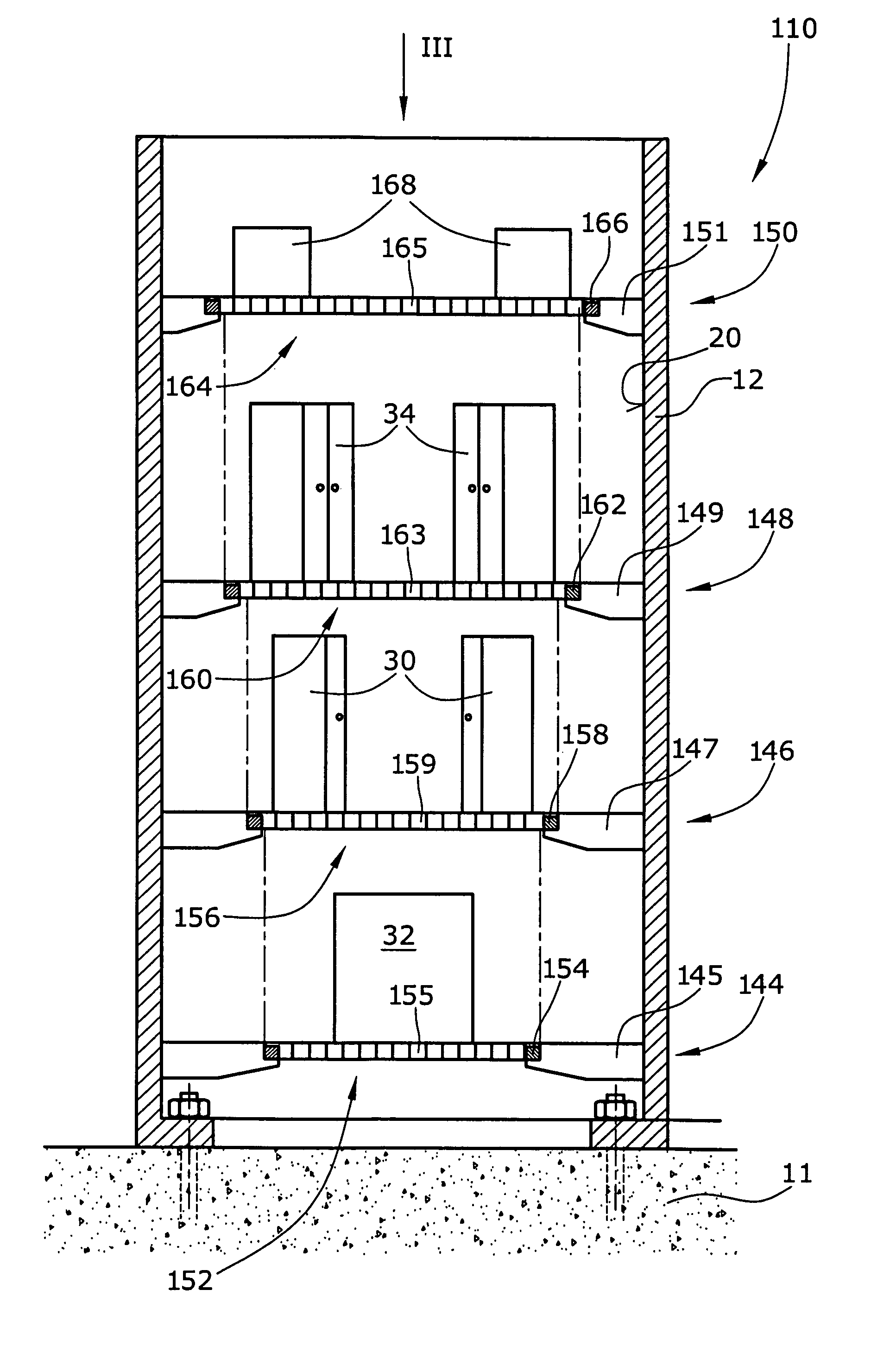
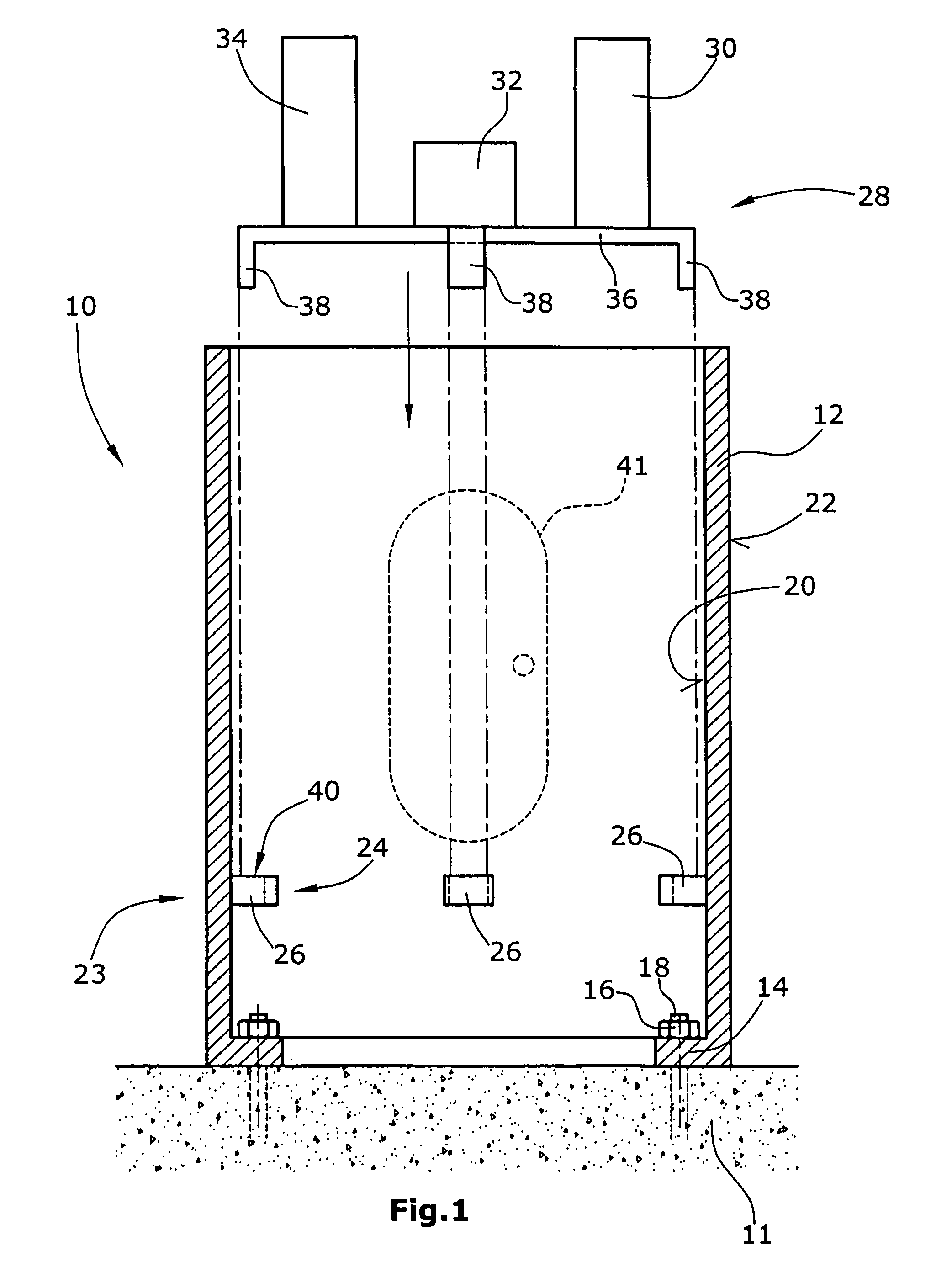
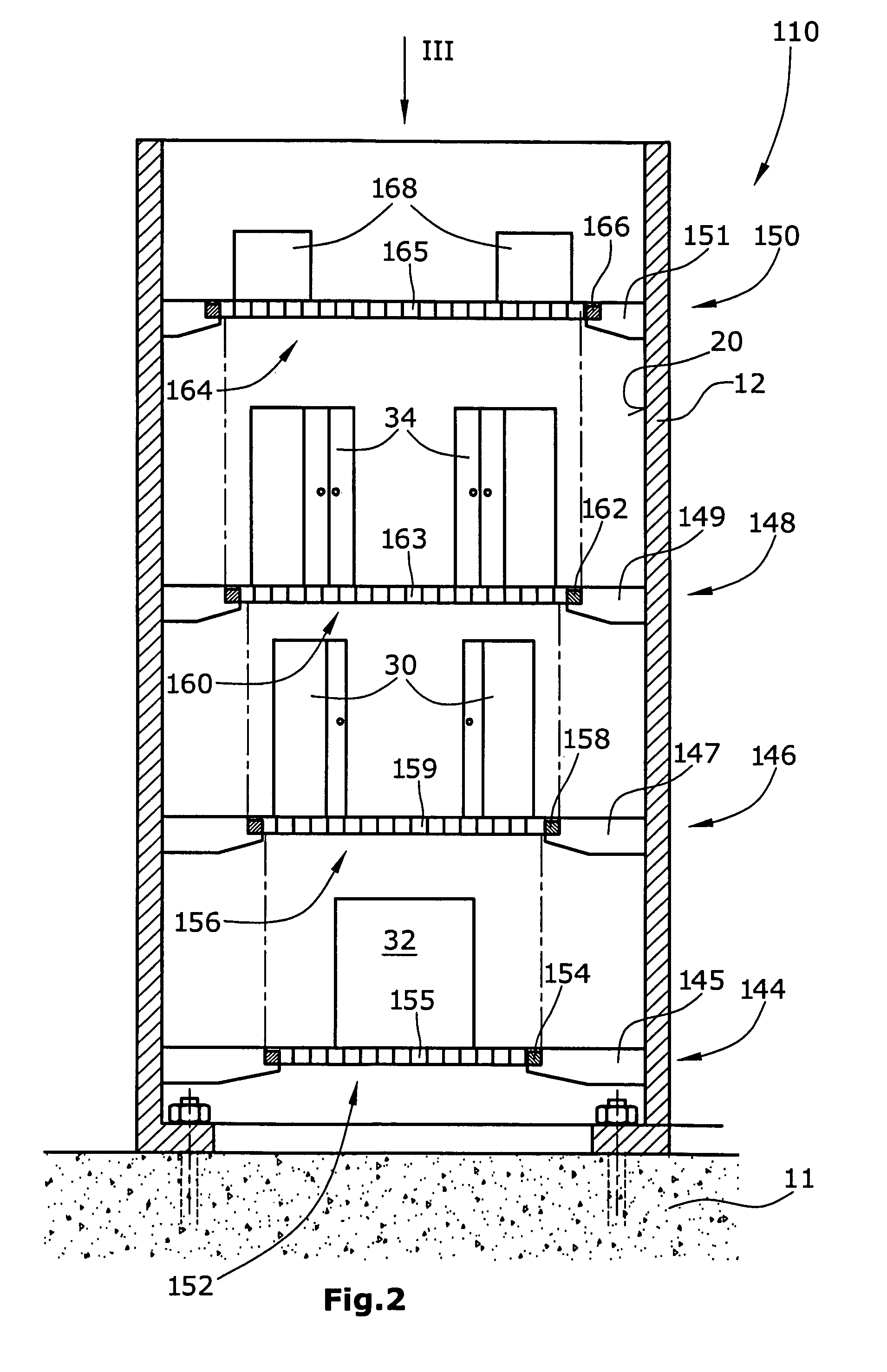
[0016]FIG. 1 depicts a tower segment 10 according to a first embodiment of the invention for the tower of a wind energy turbine (both not shown) erected and supported on a foundation 11. Tower segment 10 includes a tubular section 12 having an inner flange 14 mounted e.g. by means of screws 16 to anchoring elements 18 embedded in foundation 11. Tubular section 12 is of a cylindrical shape and includes a cylindrical inner side 20 and cylindrical outer side 22. At inner side 20 of tubular section 12 which e.g. can be made from a metal such as steel or the like, there are arranged a group 23 of supporting elements 24 in the form of a substantially U-shaped bracket 26. In the embodiment illustrated in FIG. 1, these supporting elements 24 are arranged substantially at ...


PUM


Abstract

The segment for a tower of a wind energy turbine comprises a tubular section having a longitudinal axis and inner and outer sides, and at least one group of supporting elements arranged at the inner side of the tubular section. The segment further comprises at least one platform supportable by the supporting elements of the at least one group of supporting elements.

Description

BACKGROUND OF THE INVENTION[0001]The present invention relates to the arrangement of operating components or units of a wind energy turbine in the tower thereof. More specifically the present invention relates to a segment for a tower of a wind energy turbine for arranging operating components of the wind energy turbine in the tower. In addition, the present invention also relates to a method for arranging operating components of a wind energy turbine in its tower.[0002]Modern high performance wind energy turbines often comprise a tubular tower, with diverse operating components of the wind energy turbine located internally of the tower and at the bottom thereof. These components or units are e.g. the frequency converter, the transformer and / or control systems which are necessary to supply the electrical energy from the generator to the grid.[0003]Access to the components and units located at the bottom of and within the tower is possible via a tower door located in the wall of the ...

Claims


Application Information

Patent Timeline
Patent Type & Authority Patents(United States)
IPC IPC(8): E04H12/00F16M13/00E04H5/08E04H5/00
CPCE04H12/085F03D11/00F03D11/04Y02E10/728F05B2240/40F05B2240/912F05B2230/60F03D80/00F03D13/20F03D13/22F03D80/82F03D13/10Y02E10/72Y02P70/50
Inventor MEINERS, KARL-HEINZ
Owner GENERAL ELECTRIC CO
Learn More