
Slot interface access device and slot interface access method

a slot interface and access device technology, applied in the field of slot interface access devices and slot interface access devices, can solve the problems of inability of main devices to use all functions of a certain main device, restrictions on the use of functions of other main devices on the network, and inability of each system to know information, states, and the like of resources of other systems, etc., to achieve the effect of improving affinity of the pc to the main device, high performance and large-scal

Active Publication Date: 2010-07-20
NEC PLATFORMS LTD
View PDF17 Cites 2 Cited by
  • Summary
  • Abstract
  • Description
  • Claims
  • Application Information

AI Technical Summary

Benefits of technology

This solution enables unrestricted resource sharing among main devices, reduces CPU load on the master device, and allows for a larger-scale networking system architecture with improved affinity to external applications by using high-performance PCs as master devices.

Problems solved by technology

The non-alternated functions are not compliant with the network, so that the other main devices are incapable of using all functions of a certain main device via the network.
Due to this, to enable each of the main devices to actuate the functions of the other main devices via the network is not so simple as actuating its own functions but it is disadvantageously necessary to alter the functions so as to be compliant with the network.
Due to this, each system is unable to know information, states, and the like of resources of the other systems.
As a result, restrictions are imposed on use of functions of the other main devices on the network.
If the master goes down, all the main devices connected to the master become unavailable.
However, because of concentration of processings on one main device, heavy burden is cast on the CPU of the main device to disadvantageously make it impossible to control many resources.
In other words, one master main device controls all the systems on the network, disadvantageously resulting in concentration of considerable load on the master main device.

Method used


Image

  • Slot interface access device and slot interface access method
  • Slot interface access device and slot interface access method
  • Slot interface access device and slot interface access method

Examples


Embodiment Construction

[0090]An embodiment of the present invention will be described hereinafter in detail with reference to the accompanying drawings.

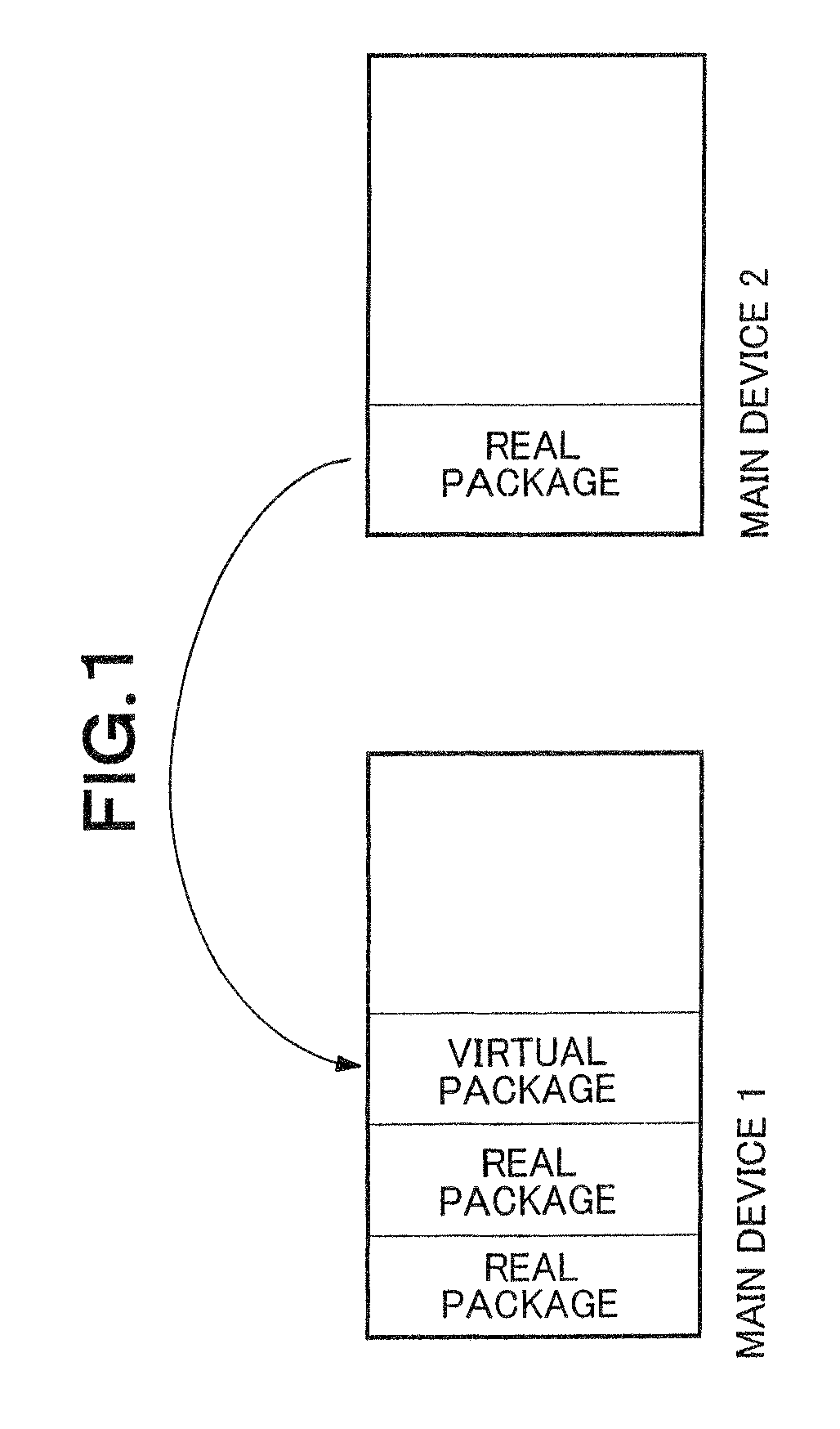
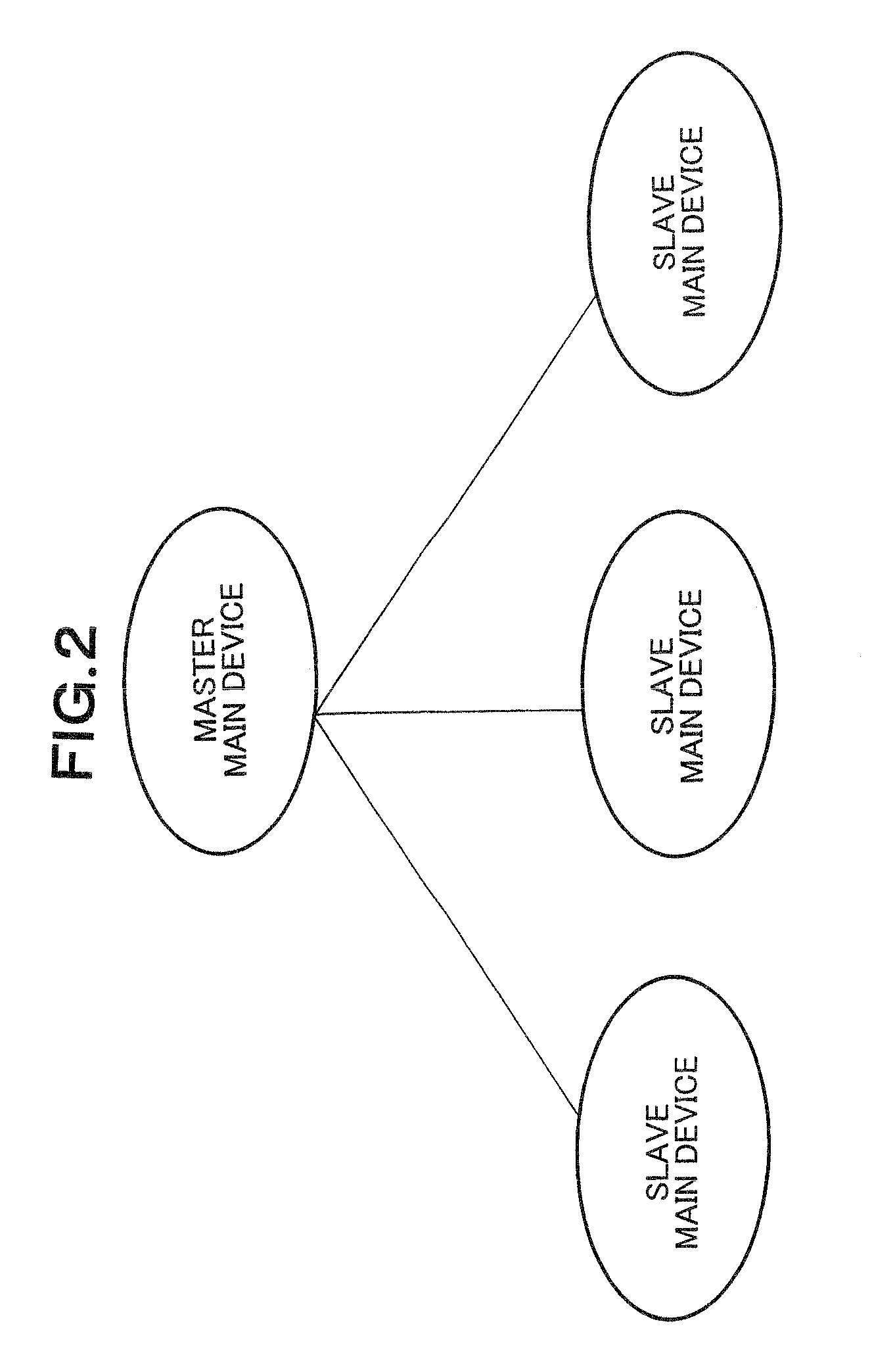
[0091]In the embodiment of the present invention, not a switchboard but a high performance general-purpose PC is used as a system that acts as a master main device, thereby avoiding the conventional problems. Namely, a similar program to the switchboard is allowed to be executed on the PC and a plurality of main devices is connected to the PC by an IP network. The PC acting as the master main device controls hardware of the main devices connected to the PC as slave main devices.

[0092]By so configuring, a high performance CPU included in the PC can be used, so that the PC can handle heavy traffic from the slave main devices.

[0093]FIG. 9 is a conceptual diagram of a resource central control networking system architecture in which the PC acts as the master main device.

[0094]FIG. 9 represents that the PC acts as the master main device and controls real main de...


PUM


Abstract

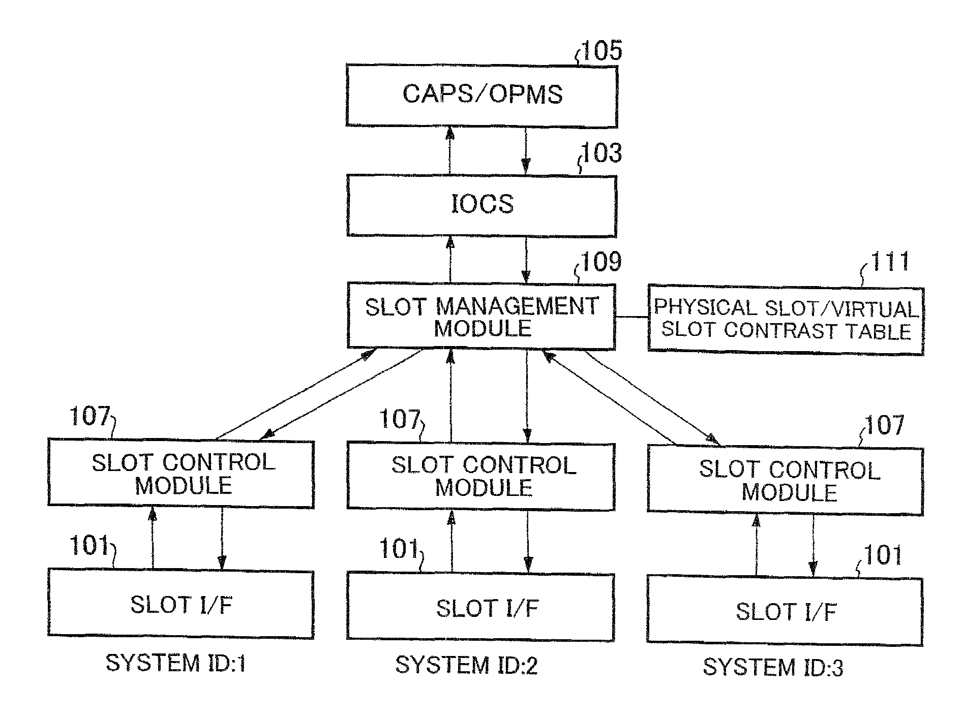
A slot interface access device including a slot management module; a slot control module; and a physical slot to management slot contrast table, the slot management module, the slot control module, and the physical slot to management slot contrast table being provided between an input and output control module and a slot interface lower than the input and output control module. The input and output control module accesses the slot interface using virtual slot identification information. The slot management module converts the virtual slot identification information into physical slot identification information while referring to the physical slot to management slot contrast table, and accesses the slot control module corresponding to the physical slot identification information, thereby realizing a physical access of the input and output control module to the slot interface. The slot interface access device is higher in CPU capability than other devices each including the slot interface.

Description

RELATED APPLICATIONS[0001]This application is based upon and claims the benefit of priority from Japanese patent application No. 2007-133960, filed on May 21, 2007, the disclosure of which is incorporated herein in its entirety by reference.BACKGROUND OF THE INVENTION[0002]1. Field of the Invention[0003]The present invention relates to a slot interface access device and a slot interface access device assembly for accessing slot interfaces present to be distributed in a plurality of main devices, and a method and a program therefor.[0004]2. Description of the Related Art[0005]There is conventionally known a technique for connecting main devices to one another by a network and for allowing each of the main devices to use functions of the other main devices as disclosed in, for example, Japanese Patent Application Laid-Open No. 2001-358736. The “main device” means herein a device that includes an interface for accommodating a terminal (e.g., a button telephone), an interface connecting...

Claims


Application Information

Patent Timeline
Patent Type & Authority Patents(United States)
IPC IPC(8): G06F13/36G06F13/00G06F13/14G06F13/38
CPCH04L12/24H04L41/00H04L69/40H04L29/1233H04L61/25H04Q2213/13003H04Q2213/13091H04Q2213/13097H04Q2213/13164H04Q2213/13166H04Q2213/13167H04Q2213/13399H04L41/40
Inventor HIKABE, AKINORI
Owner NEC PLATFORMS LTD
Learn More