
Longitudinally flexible stent

a longitudinally flexible, stent technology, applied in the field of stents, can solve the problems of low longitudinal flexibility after expansion, stress points at the end of the stent and along the cannot eliminate the stress along the entire length of the stent, so as to achieve constant density of stent elements, reduce stress, and reduce the effect of longitudinal flexibility

Inactive Publication Date: 2010-07-20
MEDINOL LTD
View PDF112 Cites 28 Cited by
  • Summary
  • Abstract
  • Description
  • Claims
  • Application Information

AI Technical Summary

Benefits of technology

[0011]Accordingly, an object of the invention is to provide a stent that is longitudinally flexible before expansion, so that it can easily be tracked down tortuous vessels and remains longitudinally flexible after expansion such that it will substantially eliminate any stress points by complying with the vessel's flexibility and assuming the natural curve of the vessel.
[0012]Another object of the present invention is to provide a stent that is longitudinally flexible after delivery such that it flexes during the cycles of the heartbeat to reduce cyclic stress at the ends of the stent and along the stent.
[0013]Another object of the present invention is to provide a stent with a closed cell pattern such that it provides good coverage and support to a vessel wall after expansion.

Problems solved by technology

One feature of stents with a cellular mesh design such as this one, however, is that they have lower longitudinal flexibility after expansion, which may be a disadvantage in particular applications.
This lower longitudinal flexibility may cause stress points at the end of the stent and along the length of the stent.
While this modification at the end of the stent alleviates the stress at the end points, it does not eliminate the stress along the entire length of the stent.
While these stents are flexible, they also have relatively unstable support after expansion.
Furthermore, these stents leave large portions of the vessel wall uncovered, allowing tissue and plaque prolapse into the lumen of the vessel.

Method used


Image

  • Longitudinally flexible stent
  • Longitudinally flexible stent
  • Longitudinally flexible stent

Examples


Embodiment Construction

[0036]FIG. 2 shows a schematic diagram of a longitudinally flexible stent 208 of the present invention. The stent 208 may be delivered to a curved vessel 210 by a balloon catheter, and implanted in the artery by inflating the balloon. As described before, the balloon causes the artery to straighten upon inflation of the balloon. However, upon deflation of the balloon, the stent 208 assumes the natural curve of the vessel 210 because it is and remains longitudinally flexible after expansion. This reduces any potential stress points at the ends of the stent and along the length of the stent. Furthermore, because the stent is longitudinally flexible after expansion, the stent will flex longitudinally with the vessel during the systolic cycles. This also reduces any cyclic stress at the ends of the stent and along the length of the stent.

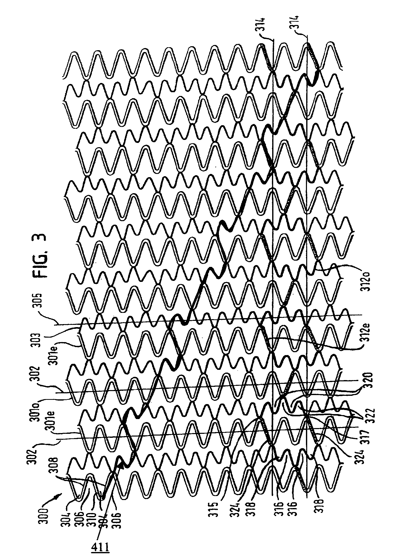
[0037]FIG. 3 shows a pattern of a stent according to the present invention. This pattern may be constructed of known materials, and for example stainle...


PUM


Abstract

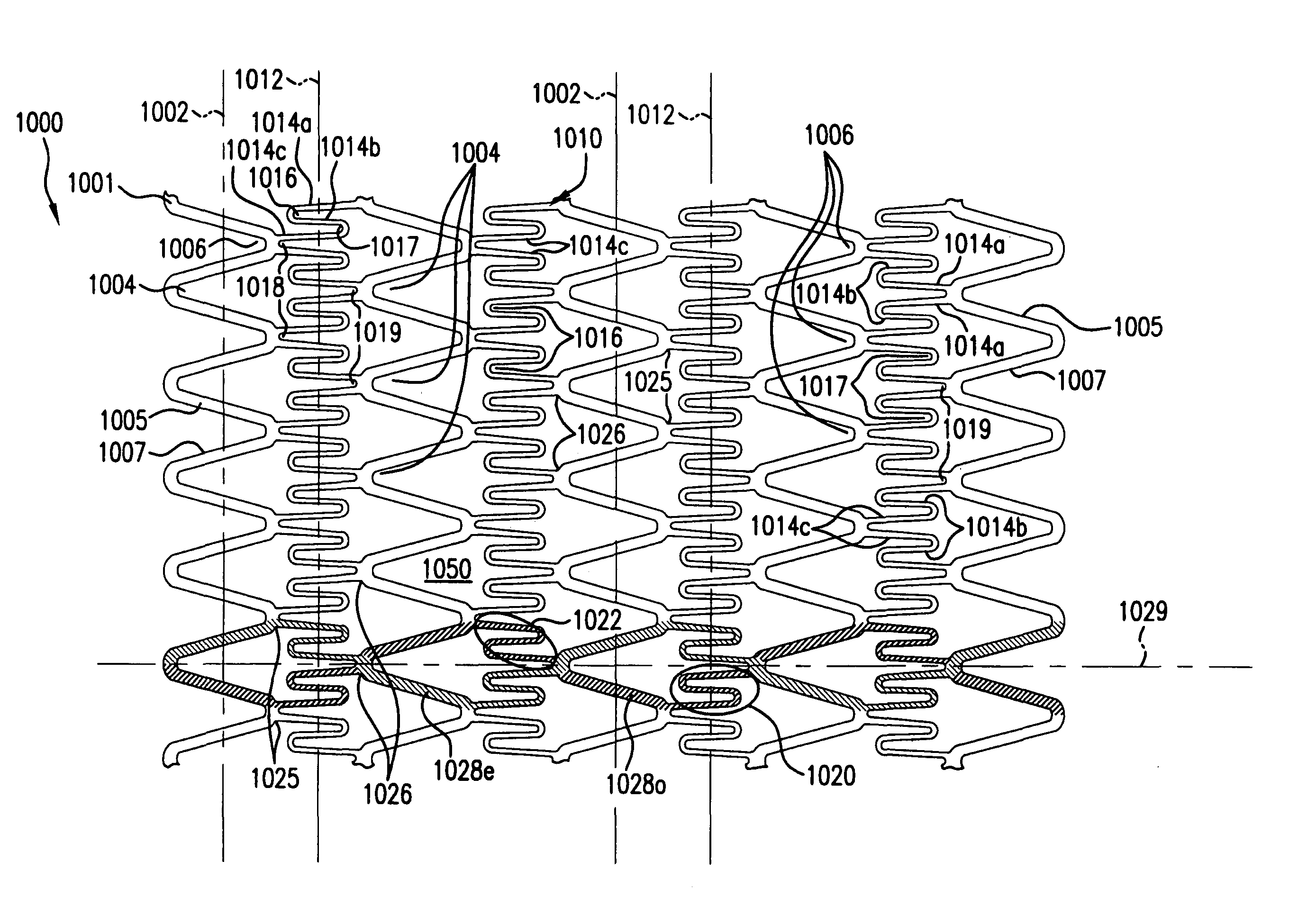
An intravascular stent especially suited for implanting in curved arterial portion. The stent retains longitudinal flexibility after expansion. The stent is formed of intertwined meander patterns forming triangular cells. The cells are adapted to provide radial support, and also provide longitudinal flexibility after expansion. The cells also provide increase coverage of a vessel wall. Loops in the stent are disposed and adapted to cooperate, so that after expansion of said stent within a curved lumen, the stent is curved and cells on the outside of the curve open in length, but narrow in width, whereas cells on the inside of the curve shorten in length, but thicken in width to maintain a density of the stent element area which is much more constant than otherwise between the inside and outside of the curve. The stent also minimizes flaring out by eliminating free loops of the radially supporting circumferential bands of loops.

Description

RELATED APPLICATIONS[0001]This application is a continuation-in-part of application Ser. No. 09 / 864,389 filed on May 25, 2001, which is a continuation-in-part of application Ser. No. 09 / 795,794 filed on Feb. 28, 2001, now U.S. Pat. No. 6,709,453 which is a non-provisional application of provisional application 60 / 202,723 filed May 8, 2000 and a continuation-in-part of application Ser. No. 09 / 516,753 filed on Mar. 1, 2000 now U.S. Pat. No. 7,141,062. The disclosures of the above-identified related applications are hereby incorporated by reference.FIELD OF THE INVENTION[0002]The present invention relates generally to stents, which are endoprostheses implanted into vessels within the body, such as, but not limited to, blood vessels, to support and hold open the vessels, or to secure and support other endoprostheses in the vessels. In particular, the present invention relates to a stent which is longitudinally flexible before and after expansion.BACKGROUND OF THE INVENTION[0003]Various ...

Claims


Application Information

Patent Timeline
IPC IPC(8): A61F2/06A61M29/00A61F2/00
CPCA61F2/91A61F2/915A61F2002/91508A61F2230/0054A61F2002/91525A61F2002/91533A61F2002/91558A61F2002/91516A61F2/86
Inventor RICHTER, JACOB
Owner MEDINOL LTD
Learn More