
Rear swing arm installation structure

a technology for installing structures and swing arms, which is applied in the direction of crankshaft transmission, cycle equipment, crankshaft transmission, etc., can solve the problems of increased manufacturing process number, increased weight, and large tightening torque, and achieve the effect of large tightening torqu

Inactive Publication Date: 2010-07-20
HONDA MOTOR CO LTD
View PDF17 Cites 3 Cited by
  • Summary
  • Abstract
  • Description
  • Claims
  • Application Information

AI Technical Summary

Benefits of technology

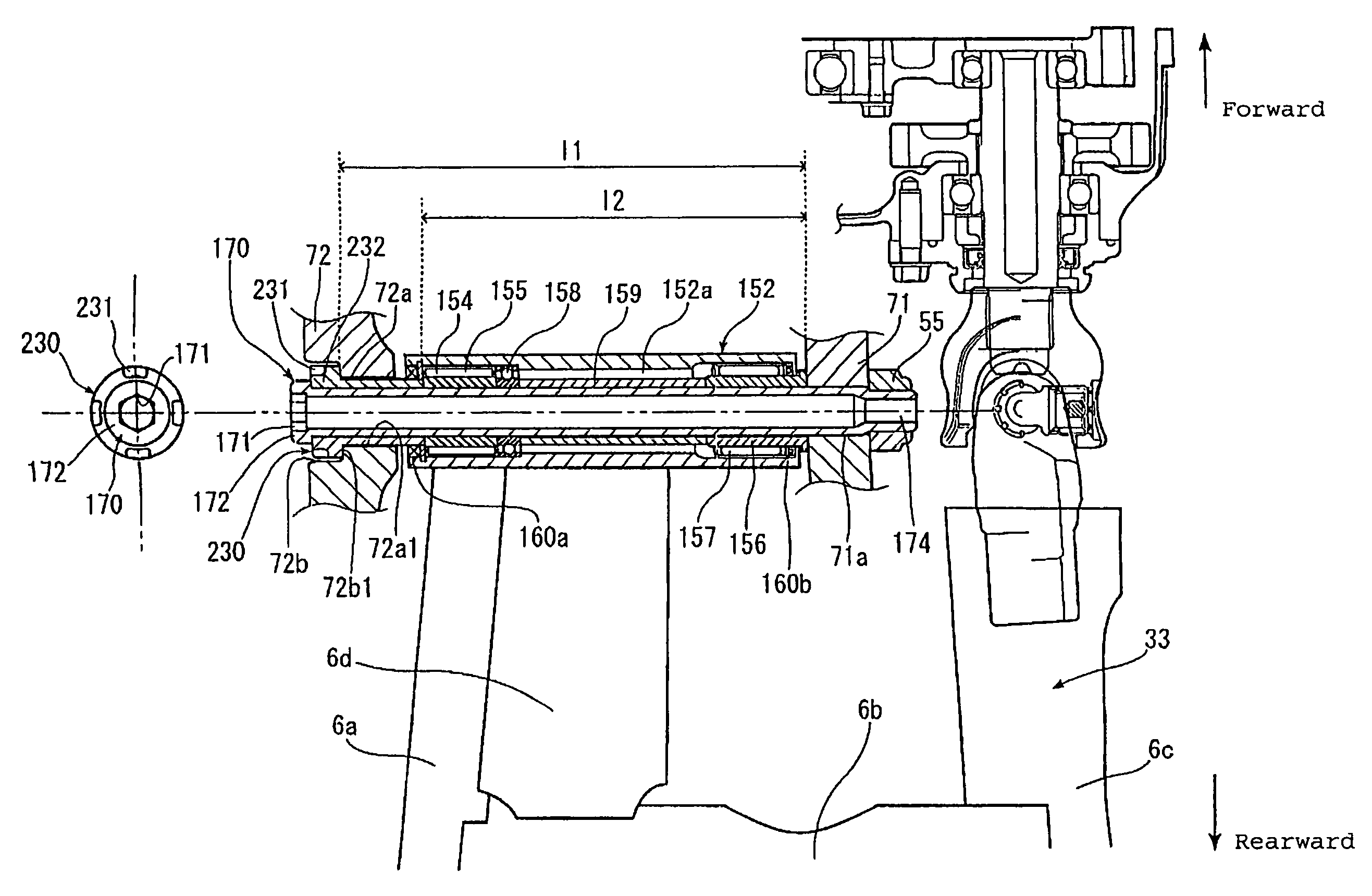
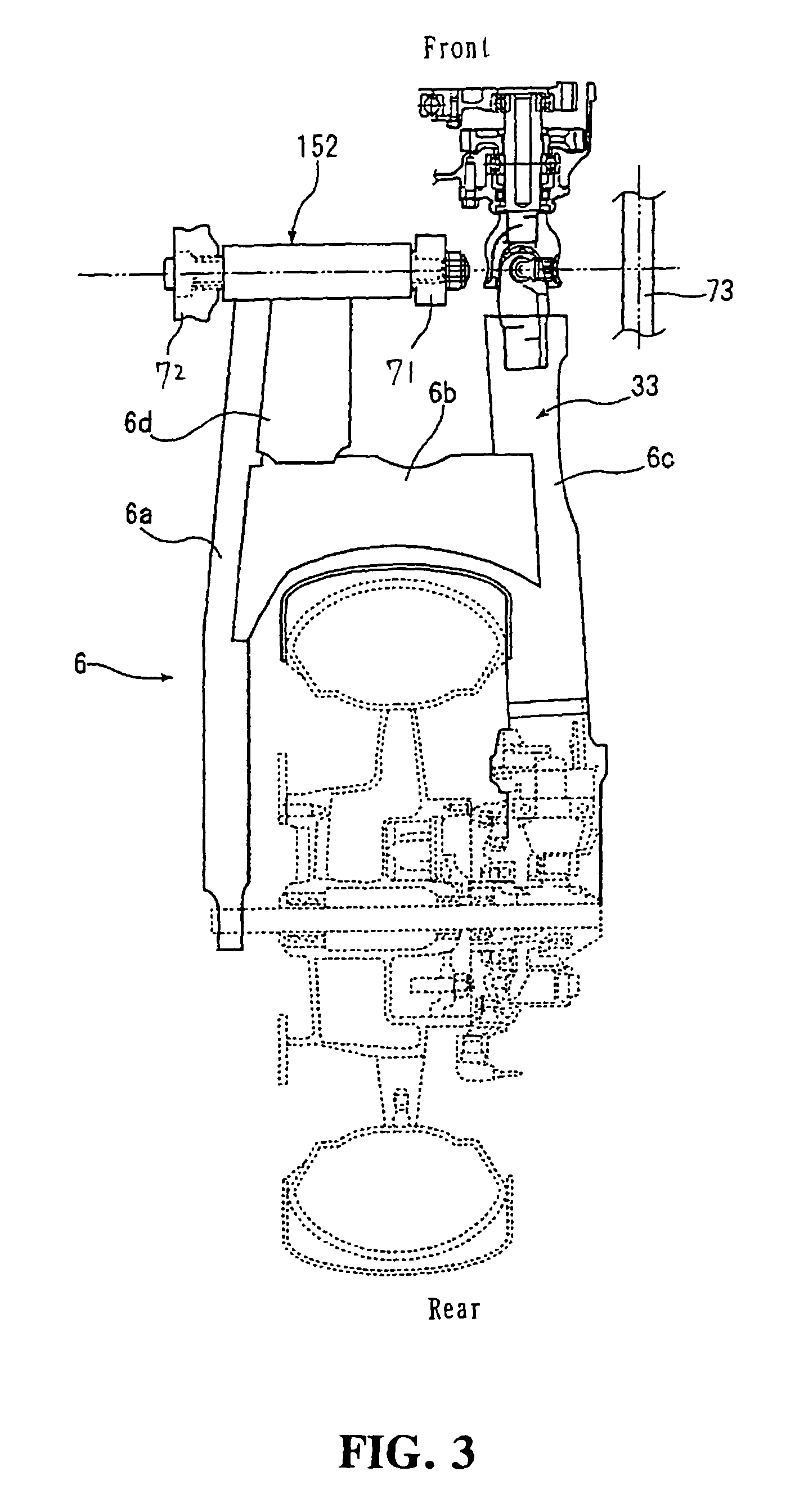
The present invention provides a rear swing arm installation structure that does not require a large tightening torque and avoids the need for upsizing. The structure includes a pivot bearing hole and an insertion hole for the rear swing arm, with a cylindrical spacer being inserted between the pivot bearing hole and the rear swing arm. The spacer has a head section and a screw section, with the head section touching the vehicle body frame and the screw section touching the rear swing arm. A recessed section is formed at the pivot bearing hole and an engaging section is formed at the head section of the spacer for easy adjustment of gaps between the rear swing arm and the vehicle body frames. The invention simplifies the installation process and reduces the number of manufacturing processes and weight.

Problems solved by technology

Thus, problems arise wherein the adjusting bolts 105a and 105b require a large tightening torque.
Thereby, an upsizing of the lock nuts 106a and 106b is required which results in an increase in the number of manufacturing processes and an increase in the weight.

Method used


Image

  • Rear swing arm installation structure
  • Rear swing arm installation structure
  • Rear swing arm installation structure

Examples


Embodiment Construction

[0022]Embodiments according to the present invention are hereunder explained in detail on the basis of the drawings.

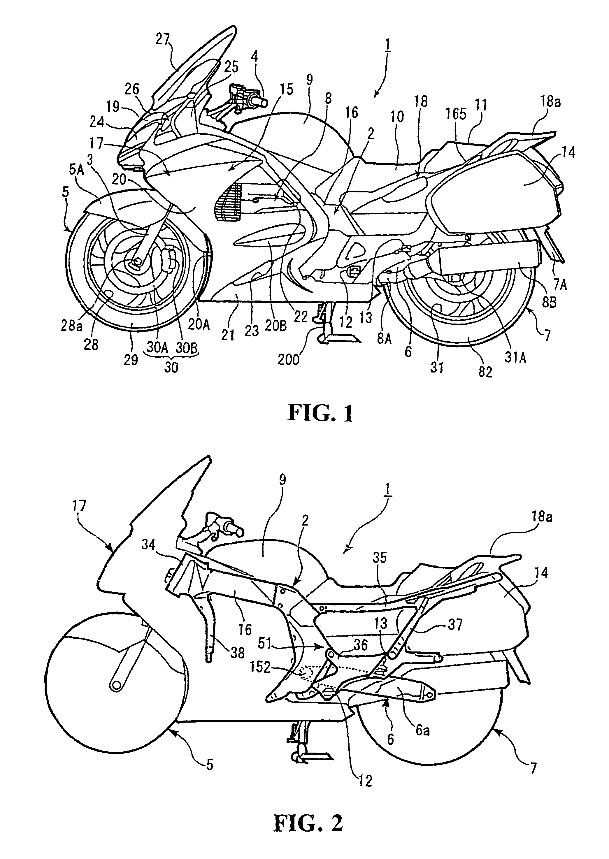
[0023]FIG. 1 is a view showing an example of a motorcycle 1 equipped with a rear swing arm installation structure of an embodiment according to the present invention. In FIG. 1, the motorcycle 1 is illustrated in the state of being supported by a stand 200.

[0024]As shown in FIG. 1, the motorcycle 1 is equipped with a vehicle body frame 2 with a pair of right and left front forks 3 rotatably supported by the front end of the vehicle body frame 2. A handlebar 4 is provided for steering and is attached to the top end of the front forks 3 with a front wheel 5 rotatably supported by the front forks 3. A rear swing arm 6 is swingably supported by the vehicle body frame 2 with a rear wheel 7 rotatably supported by the rear end of the rear swing arm 6. An engine 8 is supported by the vehicle body frame 2 with a fuel tank 9 placed above the vehicle body frame 2. A rider's seat ...


PUM


Abstract

To provide a rear swing arm installation structure that does not require large tightening force and upsizing and can avoid backlash of a rear swing arm. In a rear swing arm installation structure, a cylindrical spacer into which a pivot shaft is inserted is screwed into the pivot bearing holes of a pair of vehicle body frames. The spacer includes a head section of a large diameter and a screw section having a smaller diameter than the head section. The head section touches an end face of the pivot bearing hole of the vehicle body frame and the tip of the screw section touches an end face of a rear swing arm.

Description

CROSS-REFERENCE TO RELATED APPLICATIONS[0001]The present application claims priority under 35 USC 119 to Japanese Patent Application No. 2005-167754 filed on Jun. 8, 2005 the entire contents of which are hereby incorporated by reference.FIELD OF THE INVENTION[0002]The present invention relates to a rear swing arm installation structure of a motorcycle.DESCRIPTION OF BACKGROUND ART[0003]In a conventional rear swing arm installation structure 100, as shown in FIG. 7, pivot bearing holes 102c and 102d are coaxially drilled in a pair of vehicle body frames 102a and 102b. In addition, insertion holes 101c and 101d for a pivot bolt formed at the pivot sections of rear swing arms 101a and 101b are coaxially disposed between the pivot bearing holes 102c and 102d. Thereafter a pivot bolt 103 is inserted into the pivot bearing holes 102c and 102d and the insertion holes 101c and 101d and a nut 104 is screwed onto the pivot bolt 103. As a result, the rear swing arms 101a and 101b are in the st...

Claims


Application Information

Patent Timeline
Patent Type & Authority Patents(United States)
IPC IPC(8): B62D61/02
CPCB62K25/283
Inventor TOYODA, HIDETOSHI
Owner HONDA MOTOR CO LTD
Learn More