
Telescopic guide for drawers and similar furniture components extendable from a body of furniture

a technology of telescopic guides and drawers, which is applied in the field of fully extendable telescopic drawer guides for furniture components, can solve the problems of reducing the load-bearing capacity of telescopic guides, increasing the design complexity, and affecting the design. the effect of ease of movemen

Inactive Publication Date: 2010-07-06
ALFIT AKTIENGES
View PDF15 Cites 5 Cited by
  • Summary
  • Abstract
  • Description
  • Claims
  • Application Information

AI Technical Summary

Benefits of technology

[0003]It is therefore an object of the invention to improve the load-bearing capacity of telescopic guides of the aforedescribed type without increasing the design complexity or without impeding ease of movement.
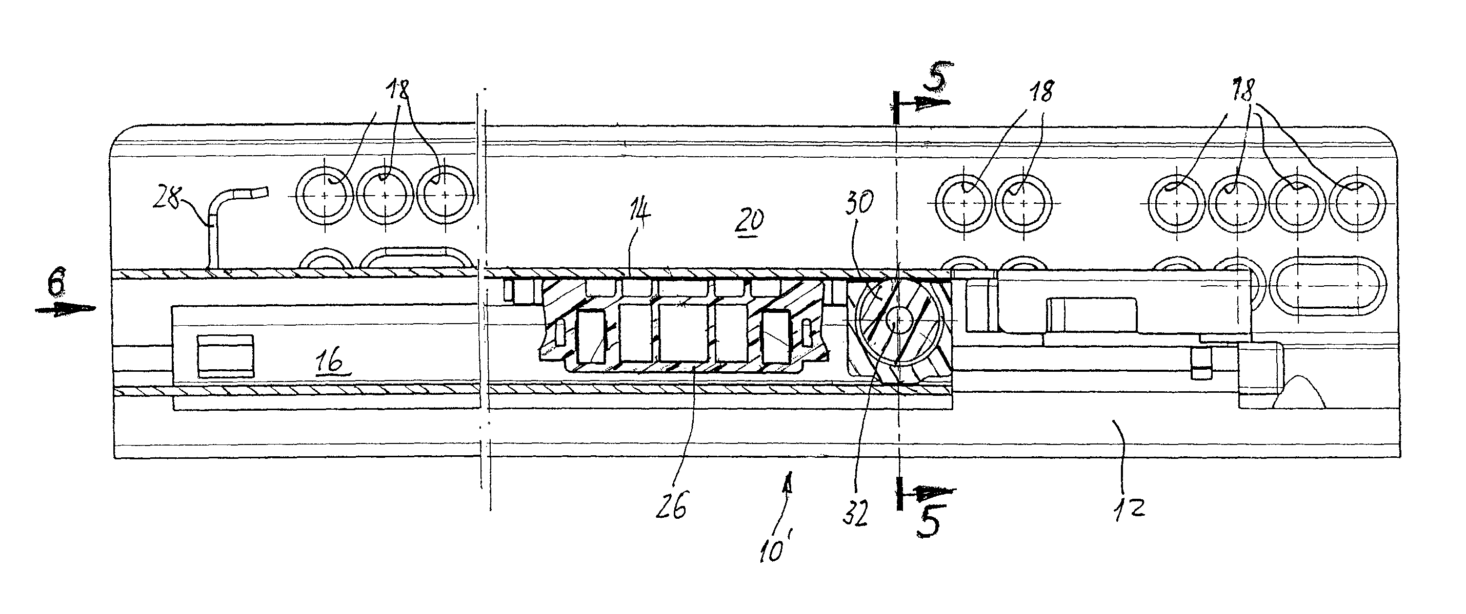
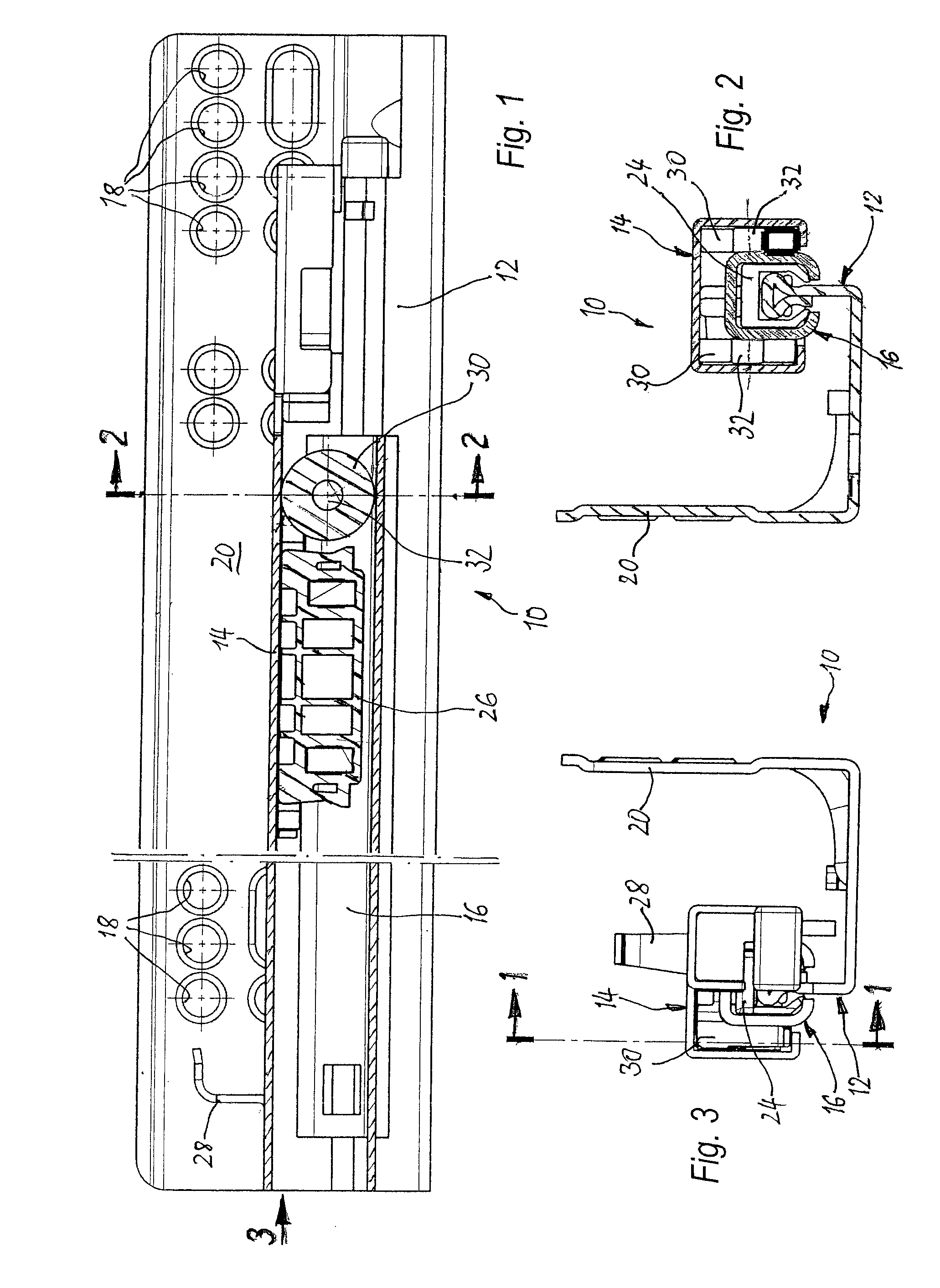
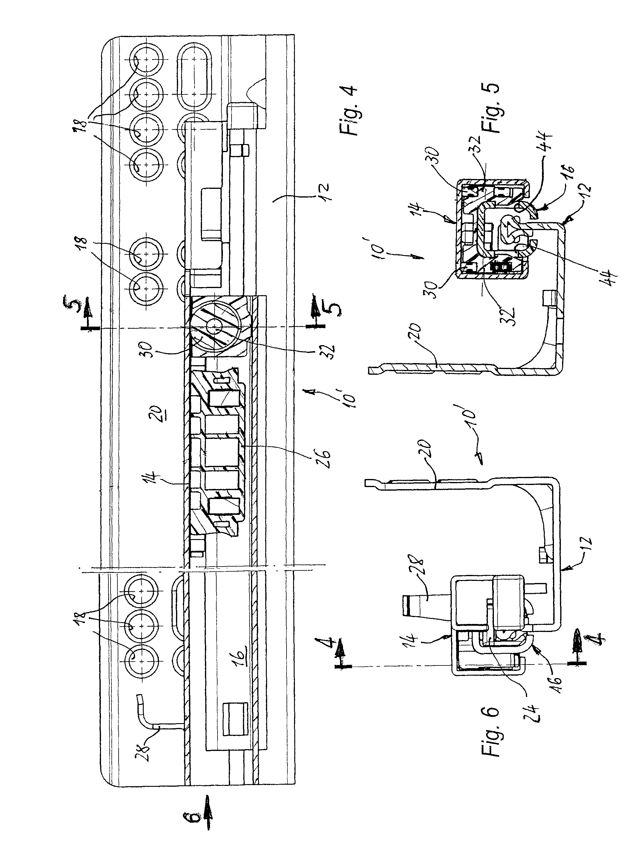
[0004]Based on a telescopic guide of the aforedescribed type, the object is solved by the invention in that the intermediate rail is implemented as a profile rail which encompasses the region of the guide rail with the rolling surfaces and which has on the bottom side an elongated opening for insertion of the support region of the guide rail to be secured to the body wall of an associated item of furniture, with the intermediate rail further including inner rolling surfaces for the rolling elements that face the rolling surfaces of the guide rail, in that the running rail is also implemented as a profile rail which also has on the bottom side an elongated opening and which encompasses the intermediate rail, and in that two supporting rollers are supported on the front end of the intermediate rail on axles that protrude horizontally from the opposing lateral profile legs of the intermediate rail perpendicular to the pull-out direction, with the peripheral surfaces of the supporting rollers being supported on rolling surfaces arranged on the inside of the running rail and extending in the pull-out direction. Both the intermediate rail and the running rail are configured as a hollow profile which is only open on the bottom side and otherwise substantially closed, with the running rail completely encompassing the intermediate rail. This makes the design of the individual rails according to the invention very compact and stable and also symmetric with respect to a vertical center plane. The weight of the drawer can then be transferred proportionally and symmetrically with respect to the aforementioned symmetry plane. As a particular advantage, the proportional load of the drawer weight can be transferred symmetrically from the running rail via the two supporting rollers, which are arranged symmetrical to the aforementioned vertical longitudinal center plane, when the drawer is open.
[0009]In another embodiment adapted for simple and quick installation of the axle support, latchingly engageable projections and openings may be provided in the regions of the U-shaped legs of the retaining member and of the lateral profile legs that face one another in the intended installation position of the axle support on the intermediate rail.
[0012]The web section of the retaining member connecting the U-shaped legs is advantageously formed so as to be elastically deformable in a center region extending in the pull-out direction, so that the U-shaped legs can elastically expand during installation on the intermediate rail and springily retract for latching engagement when the projections are aligned with the openings.

Problems solved by technology

This design is more complex in comparison to telescopic guides embodied as a simple telescopic rail with only a single guide rail and a single running rail, because the intermediate rail must be supported at two places, namely on the guide rail as well as on the running rail.
Fully extendable telescopic guides are inherently less rigid than single guides and require a more complex design to prevent elastic deformation of the rail which would cause the faceplate of an open drawer to be displaced downward, in particular when the drawer is heavy.

Method used


Image

  • Telescopic guide for drawers and similar furniture components extendable from a body of furniture
  • Telescopic guide for drawers and similar furniture components extendable from a body of furniture
  • Telescopic guide for drawers and similar furniture components extendable from a body of furniture

Examples


Embodiment Construction

[0025]FIGS. 1 to 3 illustrate a first exemplary embodiment of a telescopic guide having the overall reference symbol 10, which in the illustrated example is implemented as a fully extendable drawer. The telescopic guide is composed of three rails which are guided relative to each other for longitudinal movement, namely a guide rail 12 which can be attached to the inside surface of the side wall of the body of an item of an furniture, a running rail 14 which can be attached to an extendable furniture component, i.e., typically the drawer, in the region of the bottom side of the drawer sidewall or in an adjacent region of the drawer bottom, and an intermediate rail 16 arranged between the body and the running rail.

[0026]In the illustrated example, the guide rail 12 is a profile formed of sheet metal with a U-shaped cross-section, wherein one of the U-shaped legs forms a mounting plate 20 provided with bores 18 which can be screwed to the inside of the body sidewall of an associated ca...


PUM


Abstract

A fully extendable telescopic drawer guide (10; 10′) for furniture components, such as drawers, work surfaces and the like, that can be extended from the body of an item of furniture, with a guide rail (12) facing the body, a running rail (14) associated with the extendable furniture component, and an intermediate rail (16) arranged between these two rails, wherein rolling elements are provided which are supported in cages (24; 26) and which transfer the load of the extendable furniture component by way of rolling surfaces disposed on the rails, and wherein at least one rotatably supported supporting roller (30) for the running rail is provided on the front end of the intermediate rail. The intermediate rail (16) is implemented as a profile rail which encompasses the region of the guide rail (12) provided with the rolling surfaces and which has on the bottom side an elongated opening for insertion of the support region of the guide rail to be secured to the body wall of an associated item of furniture. The intermediate rail (16) further includes inner rolling surfaces for the rolling elements that face the rolling surfaces of the guide rail (12). The running rail is also formed as a profile rail which also has on the bottom side an elongated opening and encompasses the intermediate rail. Two supporting rollers (30) are supported on the front end of the intermediate rail on axles that protrude horizontally from the opposing lateral profile legs of the intermediate rail (16) perpendicular to the pull-out direction, with the peripheral surfaces of the supporting rollers being supported on rolling surfaces disposed on the interior of the running rail (14) and extending in the pull-out direction.

Description

BACKGROUND OF THE INVENTION[0001]The invention relates to a fully extendable telescopic drawer guide for furniture components, such as drawers, work surfaces and the like, that can be extended from the body of an item of furniture, with a guide rail facing the body, a running rail associated with the extendable furniture component, and an intermediate rail arranged between these two rails, wherein rolling elements are provided which are supported in cages and which transfer the load of the extendable furniture component by way of rolling surfaces provided on the rails, and wherein at least one rotatably supported supporting roller for the running rail is provided on the front end of the intermediate rail.[0002]Drawers and other extendable furniture components can be supported by fully extendable telescopic guides for easy movement in the body of a cabinet, so that the drawer can be fully pulled out of the body in the open position, making the content of the drawer readily accessible...

Claims


Application Information

Patent Timeline
Patent Type & Authority Patents(United States)
IPC IPC(8): A47B88/00
CPCA47B88/10A47B88/493
Inventor PRENTER, CHRISTIAN
Owner ALFIT AKTIENGES
Learn More