
Scan head rotation at different optimum angles

a scanning head and rotational technology, applied in the direction of instruments, machine supports, electromagnetic radiation sensing, etc., can solve the problems of increasing fatigue, driving users, and not giving the best solution at the rotational pivot poin

Active Publication Date: 2010-06-29
SYMBOL TECH LLC
View PDF27 Cites 16 Cited by
  • Summary
  • Abstract
  • Description
  • Claims
  • Application Information

AI Technical Summary

Benefits of technology

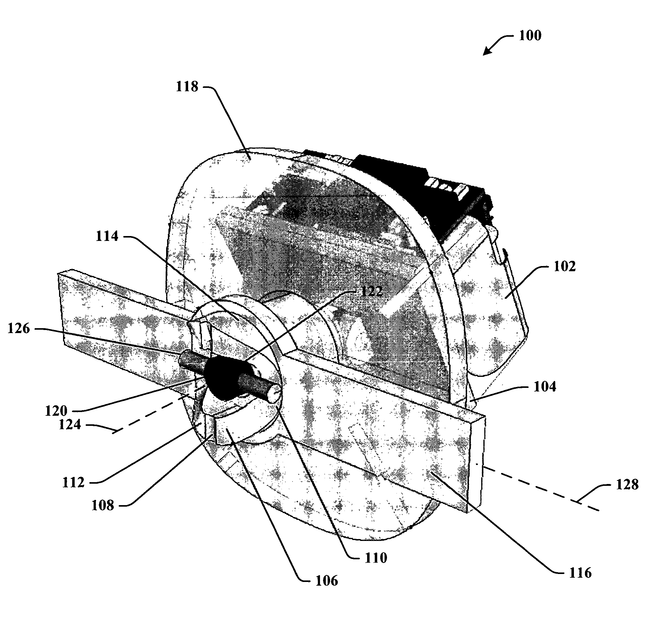
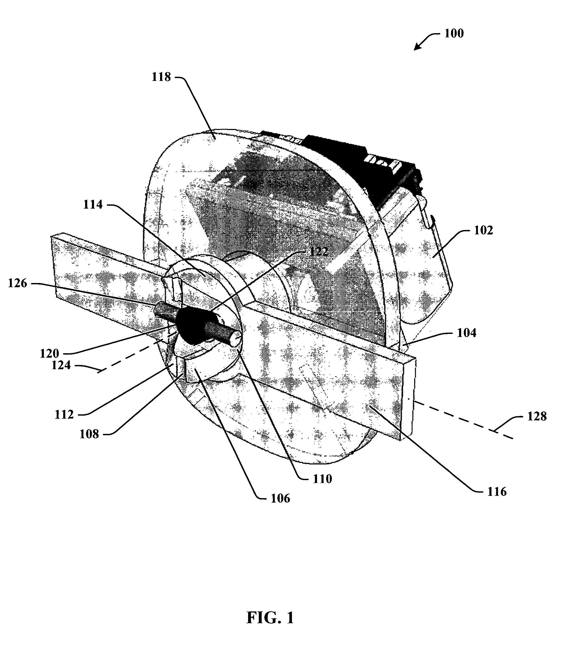
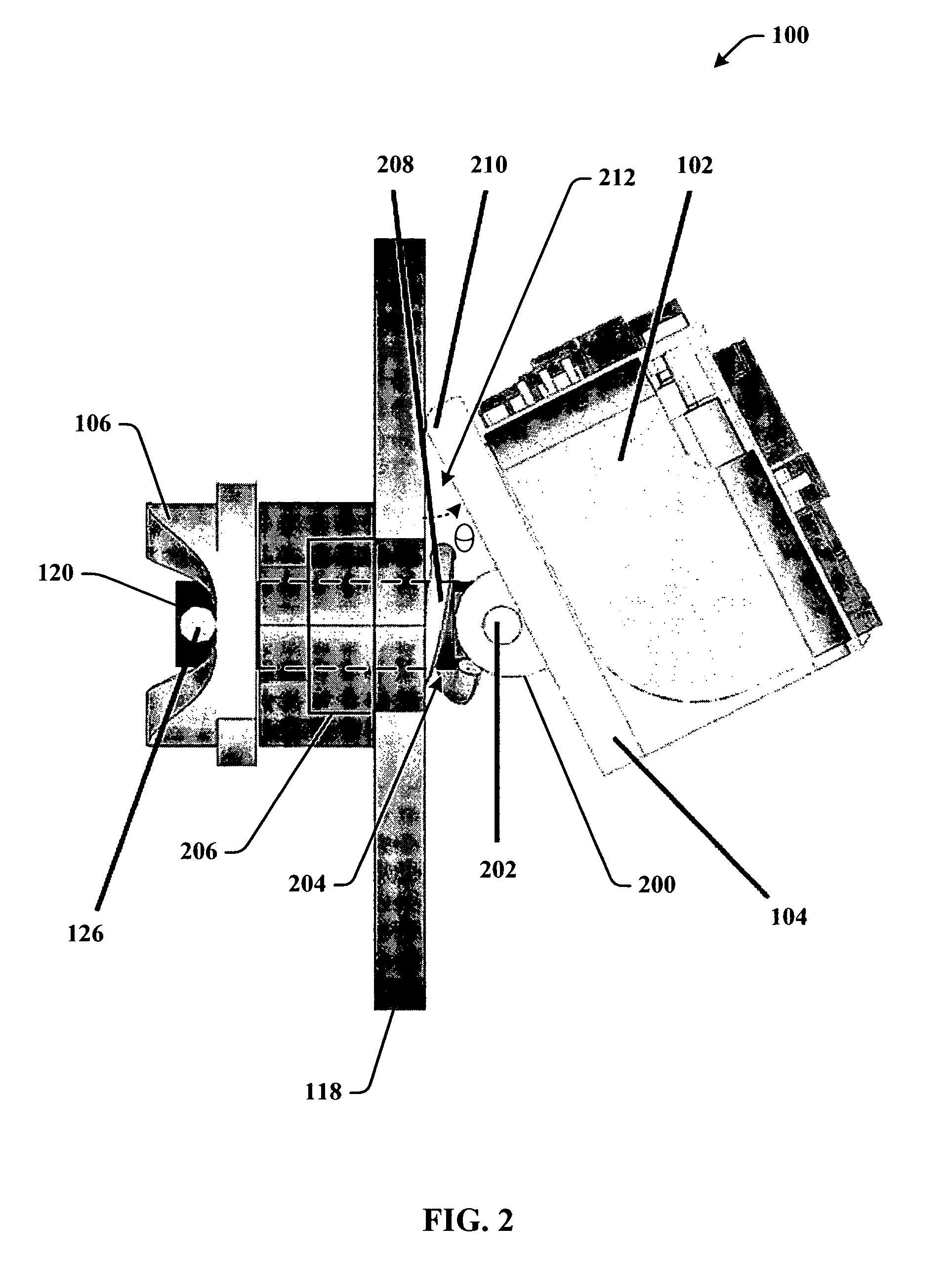
The present invention is a scan head that can be adjusted to provide an optimal angle for scanning dataforms. The scan head is rotated and mechanically adjusted to adjust the scan engine angle. The invention also includes a cam assembly that adjusts the cam height to specific angles of the scan engine. A handheld scanning device is also provided that incorporates the scan head. The invention allows for easy and efficient scanning in various angles and provides improved ergonomics for users.

Problems solved by technology

However, a single rotational pivot point does not give the best solution.
One or the other of side scanning or front scanning ergonomics gets compromised, resulting in driving the user to an undesired ergonomics, and increases fatigue during an intensive application.

Method used


Image

  • Scan head rotation at different optimum angles
  • Scan head rotation at different optimum angles
  • Scan head rotation at different optimum angles

Examples


Embodiment Construction

[0025]The present invention is now described with reference to the drawings, wherein like reference numerals are used to refer to like elements throughout. In the following description, for purposes of explanation, numerous specific details are set forth in order to provide a thorough understanding of the present invention. It may be evident, however, that the present invention can be practiced without these specific details. In other instances, well-known structures and devices are shown in block diagram form in order to facilitate describing the present invention.

[0026]As used in this application, the terms “component” and “system” are intended to refer to a computer-related entity, either hardware, a combination of hardware and software, software, or software in execution. For example, a component can be, but is not limited to being, a process running on a processor, a processor, an object, an executable, a thread of execution, a program, and / or a computer. By way of illustration...


PUM


Abstract

A scan head adjustable for optimum ergonomic scan angles. The scan head can be rotated according to a user's preferred mode such that the angle of the scan engine can be mechanically adjusted to give the optimum angle for its use. In support thereof, a cam provides sufficient action to give the optimum angle. A rotating cam pin is utilized through the cam path in accordance with a predetermined height that adjusts to specific angles of the scan engine.

Description

TECHNICAL FIELD[0001]This invention is related to dataform scanning devices, and more specifically, to a scanning device with scan head that swivels for optimum scanning.BACKGROUND OF THE INVENTION[0002]Dataform scanning is a process that is widely used in many areas of product development, manufacture, and sale. From the individual parts to the overall product itself, systems and employees can be utilized to scan dataforms throughout all processes. Handheld scanning systems continue to evolve in order to provide the most efficient and ergonomic designs for use over longs periods of time.[0003]For example, one enhancement in data capture for retail environments combines improved ergonomics and single-line capabilities of small “point-and-scan” handheld scanners with the productivity benefits of high-performance “can't miss-first pass” omni-directional scan pattern. Such features find application in high-volume retail environments to provide a versatile, handheld scanner that increas...

Claims


Application Information

Patent Timeline
Patent Type & Authority Patents(United States)
IPC IPC(8): H04N1/04F16M11/12G06K7/10H04N1/028
CPCG06K7/10881G01S7/52
Inventor HAMILTON, ALISTAIRBHATIA, SUDHIRCHOI, JAEHO
Owner SYMBOL TECH LLC
Learn More