Backlight device and liquid crystal display device
a liquid crystal display and backlight technology, applied in lighting support devices, lighting and heating apparatus, instruments, etc., can solve problems such as inability to correct a particular color, achieve the effects of reducing brightness unevenness, eliminating brightness unevenness, and suppressing brightness unevenness or color unevenness
- Summary
- Abstract
- Description
- Claims
- Application Information
AI Technical Summary
Benefits of technology
Problems solved by technology
Method used
Image
Examples
##al example
VARIATIONAL EXAMPLE
[0092]Though each of the above embodiments is described taking an applied example of a liquid crystal television, the liquid crystal display device of the present invention is not limited to these products, but can be of course applied to any product as long as it uses liquid crystal for a display device. Applicable examples of equipment include mobile phones, personal computers, PDAs (Personal Digital Assistants), liquid crystal monitors, car navigation equipment and the like.
[0093]Further, though the present embodiment was described referring to a case that is applied to a hybrid backlight, the application is not limited to this. For example, it goes without saying that this can be applied to a full LED backlight using three color LEDs, i.e., blue, red and green LEDs with no cathode fluorescent lamp.
[0094]Further, though the present embodiment was described taking a case in which two LED substrates are connected in series in the row direction, the embodiment is ...
embodiment 3
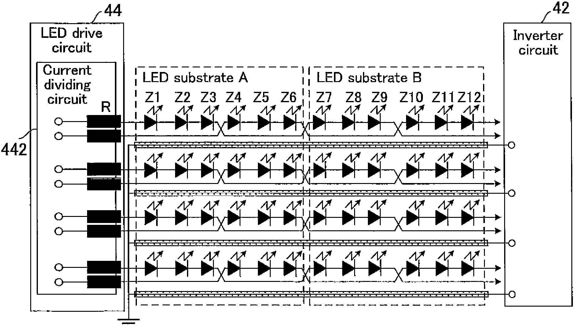
[0098]FIG. 7 shows as embodiment 4 according to the invention of the present application, a configurational example in which a serially connected one-line LED array is arranged in a twisted pattern.
[0099]As a specific configuration, a plurality of LEDs connected in series are arranged from one row to another with its one end connected via flexible cable to one of the coils as a part of the current dividing circuit on the drive circuit board. A series of three LEDs (Z1˜3) from the end in the first row on the substrate is electrically connected to a series of three LEDs (Z4˜6) positioned in the second row in the horizontal direction (the direction in which serially connected LEDs are continuously arranged in the same row). Subsequently, this is further connected again to LEDs (Z7˜) in the first row.
[0100]This is taken as a repeat unit, and the repeat units of LEDs are serially connected a plurality of times (N) in the horizontal direction. Thereafter, a wiring pattern 51 that reverses...
embodiment 4
[0103]Next, embodiment 4 according to the invention of the present application shown in FIG. 8 will be described.
[0104]The present embodiment is a developed example of the aforementioned embodiment 1 (FIG. 4), in which two lines of LED arrays serially connected from different coils of a current dividing circuit are mounted in an LED array mounting row formed for mounting a plurality of LEDs in a straight line configuration on the LED substrate, in such a manner that the two lines alternate each other with respect to the direction of arrangement of the mounting row, and each line has a turnaround portion, and the returned two lines of LEDs are mounted in another LED array mounting row on the LED substrate, in such a manner that the two lines alternate each other with respect to the direction of arrangement of the mounting row.
[0105]Illustratively, two coils 442a and 442b of current dividing circuit 442 are connected to the terminals provided at the edge of the LED substrate so that o...
PUM
 Abstract
Description
Claims
Application Information
 - R&D
- Intellectual Property
- Life Sciences
- Materials
- Tech Scout
- Unparalleled Data Quality
- Higher Quality Content
- 60% Fewer Hallucinations
Browse by: Latest US Patents, China's latest patents, Technical Efficacy Thesaurus, Application Domain, Technology Topic, Popular Technical Reports.
© 2025 PatSnap. All rights reserved.Legal|Privacy policy|Modern Slavery Act Transparency Statement|Sitemap|About US| Contact US: help@patsnap.com


