
Collapsible barrier for swimming pool, providing a safe walking path

a swimming pool and safe technology, applied in swimming pools, door/window fittings, wing accessories, etc., can solve the problems of unattractive appearance of these barriers, insufficient use, and the bulk of barriers of this type, so as to achieve quick and easy installation on site

Inactive Publication Date: 2010-06-29
ORRIERE GERARD
View PDF6 Cites 2 Cited by
  • Summary
  • Abstract
  • Description
  • Claims
  • Application Information

AI Technical Summary

Benefits of technology

"The present invention is a collapsible barrier for enclosing a swimming pool that features a simple, low-bulk structure that can be easily installed on-site without requiring modifications to the pool's edges. The barrier is designed to be motorized, with a hinge-connected ground panel that offers a comfortable and safe walking surface when the barrier is in the deployed position. The barrier's struts are offset to create a continuous surface when in the collapsed position, allowing it to be used as a deck. The barrier is equipped with means of maneuvering the enclosure panel between the barrier's erect and collapsed positions. The motor unit is placed under the ground panel to avoid interfering with traffic. The invention offers a solution for creating a collapsible barrier for a swimming pool that is easy to install, offers a continuous surface for safety, and is aesthetically pleasing."

Problems solved by technology

One problem presented lies in the unattractive appearance of these barriers, and in their bulk.
Moreover, when the swimming pool is being supervised, their presence is rendered useless.
Furthermore, this barriers of this type are still bulky, all the more because they are equipped with motorized devices for maneuvering them.
However, if this type of accentuation allows the barrier to be used in the collapsed position, its bulk is still significant and its installation on site involves the addition of accessories around the edges of the pool.
In fact, the grid-like structure of these panels means that when the barrier is in the deployed position, the walking path formed by the ground panel does not provide sufficiently comfortable stability for the user, or even the option of a safe travel path.
Moreover, the methods used for the motorized operation of the enclosure panel are still bulky, and are a source of interference for the user, especially with regard to ease of traffic flow around the pool when the barrier is in the erect position.

Method used


Image

  • Collapsible barrier for swimming pool, providing a safe walking path
  • Collapsible barrier for swimming pool, providing a safe walking path
  • Collapsible barrier for swimming pool, providing a safe walking path

Examples


Embodiment Construction

[0022]The motor unit, specifically consisting of the electric motor with rotary shafts, is preferably housed inside a caisson made inside an open space made in the surface around the pool, preferably located at the ends of the edges of the barrier, on the outer side of said barrier relative to the pool.

[0023]It will be understood that the two variations of embodiment of the motorized means can be used as a complement to each other for operating the respective enclosure panels.

[0024]More specifically, the panels comprising the sides of the barrier can be operated by cylinders, specifically hydraulic cylinders, whereas the end panels of these sides can be operated by the electric motor unit with dual rotary shafts.

DESCRIPTION OF FIGURES

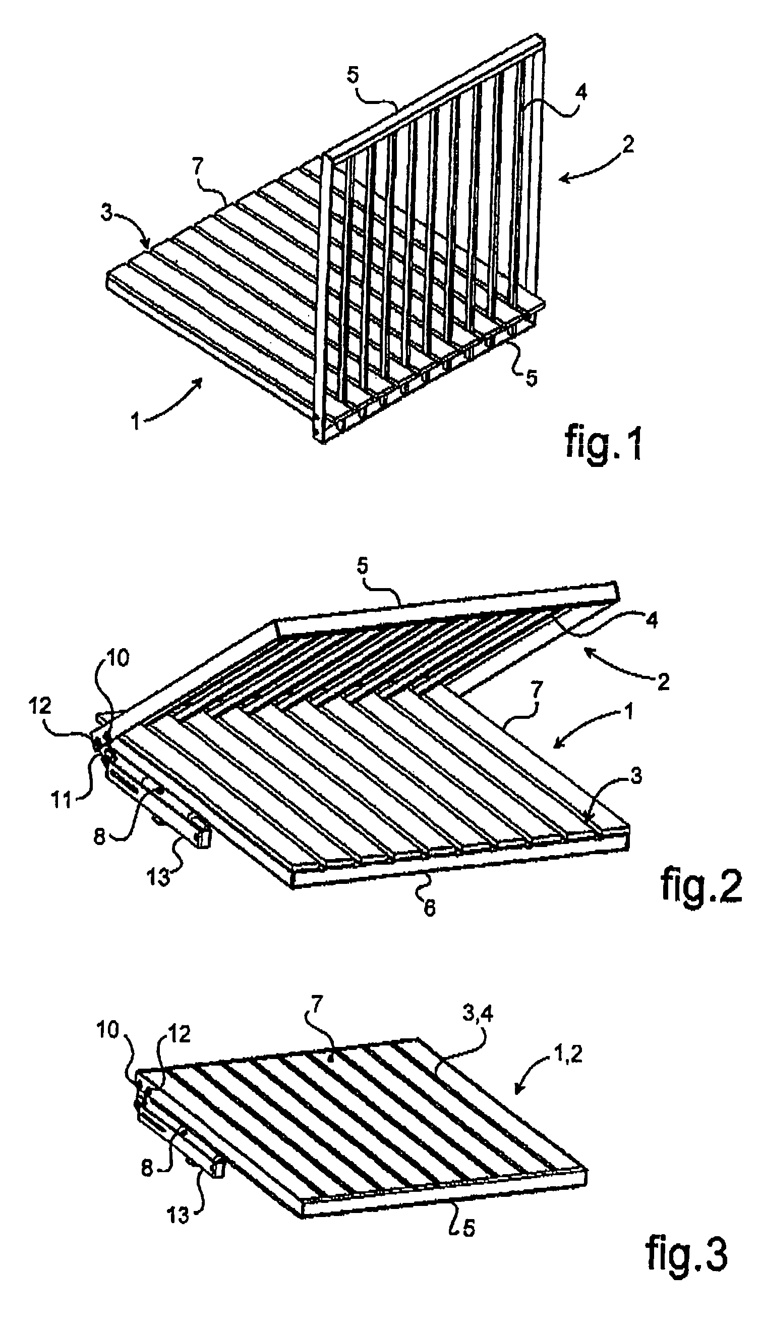
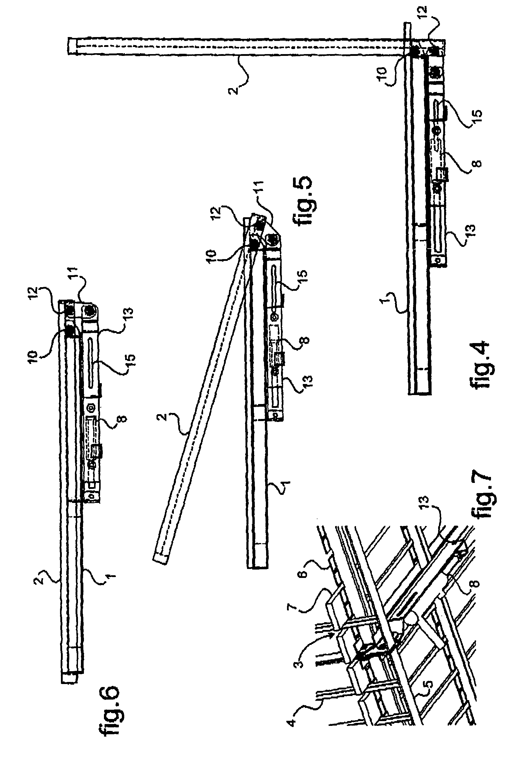
[0025]The present invention will be better understood, and the relevant details will become apparent, from the following description with reference to the figures in the attached drawings, in which:

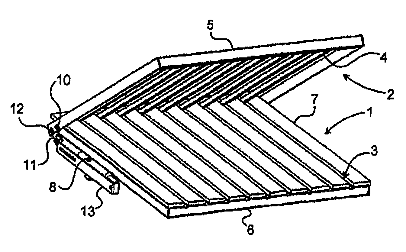
[0026]FIGS. 1 through 3 are perspective diagrams of one...


PUM


Abstract

A collapsible barrier to enclose a body of water, maneuverable between a deployed enclosure position and a collapsed position which barrier is comprised of panels articulated to each other, a ground panel (1) and an enclosure panel (2) which panels are formed from struts (4,7) supported by side rails (5,6), the struts (7) of the ground panel (1) together comprise a plate in which slits (3) are made through which the enclosure panel (2) struts, consisting of rods (4), can pass, so that in the deployed position of the barrier, the walkway surface provided by the ground panel (1) is nearly continuous.

Description

[0001]This application is a 371 of PCT / FR2005 / 003071 filed Dec. 7, 2005.TECHNICAL DOMAIN OF THE INVENTION[0002]The present invention is in the domain of safety devices for water expanses, specifically swimming pools, and more specifically the domain of enclosure barriers for a pool. Its object is a collapsible barrier, which can be maneuvered between a deployed position, in which the barrier fences the pool off, and a folded position, in which the barrier is collapsed to allow access to the pool.STATE OF THE ART[0003]For safety reasons, expanses of water, such as a swimming pool or similar, must be fenced in when they are not in use or when they are left without supervision. These provisions are intended specifically to prevent accidents by drowning, especially of children, by preventing access to the pool. It is therefore standard practice to provide expanses of water with enclosure barriers.[0004]One problem presented lies in the unattractive appearance of these barriers, and in t...

Claims


Application Information

Patent Timeline
Patent Type & Authority Patents(United States)
IPC IPC(8): E06B11/00
CPCE04H4/06
Inventor ORRIERE, GERARD
Owner ORRIERE GERARD
Learn More